background image


  ZXV10 W615 User Manual

Confidential and Proprietary Information of ZTE CORPORATION 51


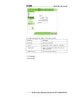
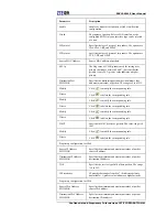
Parameter Description 

Address 

End Destination IP 
Address 

End IP address of the destination. 

Start source port 

Port number of the start source (LAN side) address. 

End source port 

Port number of the end source (LAN side) address. 

Start Destination port 

Port number of the start destination source (LAN side) 
address. 

End Destination port 

Port number of the end destination source (LAN side) 
address. 

Ingress 

The availbable options are LAN, 
IGD.WD1.WCD1.WCIP1, or blank. It is blank by default, 
which refers to any mode. 

Egress 

The availbable options are LAN, 
IGD.WD1.WCD1.WCIP1 or blank. It is blank by default, 
which refers to any mode. 

Mode 

Select a filtering mode: Discard or Permit. 

Modify 

Click 

  to modify the corresponding IP filter rule. 

Delete 

Click 

  to delete the corresponding IP filter rule. 


3. Click 

Add

—END


OF


STEPS—


Setting


MAC


Filter


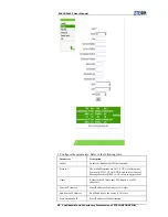
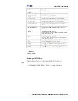
This section describes how to filter the prohibited MAC addresses. 

Steps 

1. Select 

Security > MAC Filter

. The following page is displayed. 

Summary of Contents for ZXV10 W615

Page 1: ...615 Outdoor Wireless Access Point User Manual Verson V3 0 ZTE CORPORATION NO 55 Hi tech Road South ShenZhen P R China Postcode 518057 Tel 86 755 26770801 URL http ensupport zte com cn E mail support zte com cn ...

Page 2: ... by any means electronic or mechanical including photocopying and microfilm without the prior written permission of ZTE Corporation The manual is published by ZTE Corporation We reserve the right to make modifications on print errors or update specifications without prior notice Version No RVerson V3 0 Edition Time 2012 08 20 R1 0 Manual No SJ 20120820095015 001 ...

Page 3: ... ZXV10 W615 provides a highly secure system for Wireless Local Area Network WLAN By supporting Power over Ethernet PoE ZXV10 W615 acquires convenient power supply Typical Application The device is typically used in the following scenarios Small and medium sized enterprises To realize wireless coverage and meet mobile office requirements Remote access to the company network To receive and send E ma...

Page 4: ... and retailers to share information through mobile access to the database Family office users To meet the requirement for installing a small computer network easily and quickly Interface and Button Description For a description of the interfaces and buttons of the ZXV10 W615 refer to the following table Name Description Ethernet LAN interface PoE supports 10 100 1000 Mbps connected by an RJ 45 net...

Page 5: ...dity 5 RH to 100 RH IP Protection Class IP protection class IP66 Passed Certifications CCCi Wi Fi RoHS ZTE Corporation reserves the right to modify technical parameters with this manual without notice Antenna Requirement Antenna Type N type Dipole Antenna Frequency MHz Gain dBi 2400 1 0 2410 1 2 2420 1 1 2430 1 2 2440 0 9 2450 1 0 2460 1 1 2470 1 0 2480 1 2 2490 1 4 2500 1 1 5220 2 98 5765 3 43 ...

Page 6: ... page of the ZXV10 W615 device is displayed Notes The initial user name and password of a common user are both user This user has only the authority to view the related Status information of this device The initial user name and password of the administrator are both admin This user has the authority to configure and manage the device through the Web browser For the factory defaults of ZXV10 W615 ...

Page 7: ...t Configuration Protocol DHCP applicable for fit AP only WAN mode DHCP Wireless mode Network card 1 Mixed 802 11b 802 11g Network card 2 Mixed 802 11a 802 11n SSID SSID1 is enabled Introduction to the GUI for Software Setup After log in the software interface is displayed as Figure 1 Figure 1 Software Interface 1 Main menu 2 Submenu 3 Parameter Select items on the main menu for software setup Sele...

Page 8: ...of the current Web page Then the system log outs and returns to the Login page Click at the bottom of the navigation pane to view the related help information on the current page Click the Help tab to open the Help page to view the related help information Click at the top of the current web page to change the language to chinese ...

Page 9: ...ck the device information Steps Select Status Device Information to open the Device Information page Device information is displayed on the Device Information page as Figure 2 Figure 2 Device Information Notes This page includes the information of model serial no batch number hardware version software version boot loader version and AP name END OF STEPS ...

Page 10: ...nterface information is displayed Figure 3 Ethernet Interface Information Notes This page includes Ethernet port MAC address status mode packets received bytes received and packets sent bytes sent information You can click Refresh to view the latest Ethernet interface information END OF STEPS Checking WAN Connection This section describes how to check the network connection information Steps Selec...

Page 11: ...tion IP DNS Domain Name Server Gateway Connection status remaining lease time You can click Refresh to view the latest WAN connection information END OF STEPS Checking WLAN Interface Information This section describes how to check the WLAN interface information Steps Select Status User Interface WLAN the following page is displayed In the right pane view the WLAN interface information ...

Page 12: ...e the channel the WDS mode if the WDS is enabled the MAC address of the WDS interface the MAC address of the relay the root AP and the connection state is displayed and the SSID enabled state You can click Refresh below the drop down scroll bar It isn t displayed in the above figure for the limitation on the figure size to view the latest device information END OF STEPS ...

Page 13: ... Connection Fit AP The ZXV10 W615 has two operational modes fat AP and fit AP The default operational mode is fit AP Context For instructions on how to change the AP mode for the ZXV10 W615 refer to Setting the AP Mode Notes After the AP mode is changed the device restarts automatically Steps 1 Select Network WAN WAN Connection The following page is displayed ...

Page 14: ...Includes DHCP Static DNS and Broadcast The default setting is DHCP AC Type Set AC Type When AC Type is set to Adapter the AP selects the uplink AC automatically AC Name This parameter is configurable when AC Discovery Mode is DHCP or DNS Enable CAPWAP Encryption Enables or disables CAPWAP encryption WAN Type When IP Version is IPv4 the supported modes are DHCP Static and PPPoE When IP version is I...

Page 15: ...g priority It only applies to multiple WAN connections The range is 0 7 and the default value is 0 which means no priority A greater value indicates a higher priority Enable DSCP Enables or disables the Differential Services Code Point DSCP function for data flow DSCP Specifies the DSCP value The value range is 0 63 MTU Specifies the Maximum Transmission Unit MTU value The default value is 1448 3 ...

Page 16: ...en IP Version is IPv4 the supported modes are DHCP Static and PPPoE When IP version is IPv6 or IPv4 v6 the supported modes are DHCP and PPPoE The default mode is DHCP 3 Click Submit Notes The configuration on this page takes effect after the device is restarted END OF STEPS WLAN Configuration Setting Basic Information This section describes how to set WLAN information for the ZXV10 W615 Context Tw...

Page 17: ...he basic parameters of WLAN If Network Card 1 is selected see the previous figure for the configuration page For a description of the parameters refer to the following table Parameter Description Network Card Select network card 1 Enable Wireless RF Enables or disables the wireless RF function Enable Isolation Enables or disables the SSID isolation function Mode Supports IEEE 802 11b Only IEEE 802...

Page 18: ...imum Clients Specifies the maximum number of connected users The range is 1 512 SGI Enable Enables or disables the SGI function A MPDU Enable Enables or disables the A MPDU function Beacon Interval Specifies the beacon interval Power Type Supports configuration by percent configuration based on actual power value unit dBm and configuration based on actual power value unit mW Transmitting Power Sup...

Page 19: ...cription of the parameters refer to the following table Parameter Description Network Card Select network card 2 Enable Wireless RF Enables or disables the WLAN RF function Enable Isolation Enables or disables the SSID isolation function Mode Supports IEEE 802 11a Only IEEE 802 11n Only and Mixed 802 11a 802 11n The default is Mixed 802 11a 802 11n Country Region United States of America Band 5G B...

Page 20: ...ration based on actual power value unit dBm and configuration based on actual power value unit mW Transmitting Power Supports automatic 100 90 80 70 60 50 40 30 20 12 5 and 10 The default is 100 The power class refers to the percentage of output power to maximum power A higher power indicates a farther transmission distance QoS Type The options are Disabled WMM and SSID RTS Threshold Specifies the...

Page 21: ...ID16 correspond to network card 1 SSID17 SSID32 correspond to network card 2 Hide SSID Determines whether to hide this SSID Enable SSID Enables or disables this SSID Enable SSID Isolation Enables or disables the isolation within this SSID Isolation Mode Specifies an appropriate isolation mode from four modes which are Unicast Broadcast Multicast and ALL The default setting is ALL Maximum Clients S...

Page 22: ... 4094 802 1p Specifies the processing priority The range is 0 7 The default value is 0 which means no priority A greater value indicates a higher priority As Management SSID Disabled by default When this function is enabled the user associated with the SSID can manage the device 3 Click Submit END OF STEPS Setting Security Information This section describes how to set WLAN security information Ste...

Page 23: ...ating interval The default is 600 seconds WPA Encryption Algorithm Supports TKIP AES and TKIP AES Authentication Type is divided into non encryption WPA PSK encryption WPA EAP encryption WEP encryption WAPI PSK encryption and WAPI CERT encryption non encryption Authentication Type selects Open System meaning non encryption WPA PSK encryption WPA encryption means Wi Fi protected access It has three...

Page 24: ...168 1 1 Server Port Specifies the port of the authentication server for example 1812 The range is 0 to 65535 Secret Specifies the WPA EAP encryption key The range is 1 64 characters Reauth Period The default is 3600 seconds Enable Preauth Enables or disables the pre authentication function The function is disabled by default Enable WPA Group Key Update Enables or disables WPA group key updating fu...

Page 25: ...sed WLAN security protocol i Select Shared Key or Open System Shared Key for Authentication Type The following page is displayed ii Configure the parameters Refer to the following table Parameter Description WEP Encryption Enables or disables WEP encryption function The function is enabled by default WEP Encryption Level There are two types of WEP key namely 64bit and 128bit WEP Key Index Specifie...

Page 26: ...onds to 13 ASCII characters or 26 hexadecimal characters WAPI PSK encryption i Select WAPI PSK as the Authentication Type The following page is displayed ii Configure the parameters Refer to the following table Parameter Description WAPI Key Mode Supports two modes ASCII and HEX The default is ASCII WAPI Key Specifies WAPI key value The range is 8 64 characters WAPI CERT encryption i Select WAPI C...

Page 27: ...button select the proper type of certificate file in the displayed dialog box and then click Upload Notes Certificate files include AS certificate AP certificate and CA certificate If only AP and CA certificates are necessary upload the AP certificate first Otherwise upload the AS certificate first WEP EAP encryption i Select WEP EAP as the Authentication Type The following page is displayed ...

Page 28: ...address of the authentication server for example 192 168 1 1 Server Port Specifies the port of the authentication server for example 1812 The range is 0 to 65535 Secret Specifies the WPA EAP encryption key The range is 1 64 characters Reauth Period The default is 3600 s Enable Preauth Enables or disables the pre authentication function The function is disabled by default WEP Encryption Enables or ...

Page 29: ...pports SSID STA and MAC Choose SSID Specifies the SSID to be configured The range is SSID1 SSID16 SSID Downlink Rate Guarantee The configuration range is 0 250000 kbps The default is 0 which means no rate guarantee SSID Downlink Rate Limit The configuration range is 0 250000 kbps The default is 0 which means no rate limit STA Downlink Rate Limit The configuration range is 0 250000 kbps The default...

Page 30: ...ange is 0 250000 kbps The default is 0 which means no rate limit 3 Click Submit END OF STEPS Setting Access Control List The access control list is used to guarantee the device security in networks Steps 1 Select Network WLAN Access Control List The following page is displayed 2 Configure the parameters Refer to the following table Parameter Description Choose SSID Specifies the SSID to be configu...

Page 31: ...es Permit permits the access of devices with specified MAC addresses MAC Address Specifies the MAC address of the equipment to be controlled Delete Click to delete the corresponding item of control channel 3 Click Add END OF STEPS Checking Associated Devices This section describes how to check the detailed information of the devices associated with the SSID Steps 1 Select Network WLAN Associated D...

Page 32: ... the detailed information of the associated device corresponding to the SSID By default the system displays the device information associated with SSID1 Notes You can click Refresh to view the latest information END OF STEPS Scanning an AP This section describes how to scan an AP Steps 1 Select Network WLAN AP Scanning The following page is displayed ...

Page 33: ...ct the network card and channel to be scanned respectively Caution When the SSID is disabled or the WIDS mode is Access this page cannot be configured 3 Click Scan The scan result is displayed on the refreshed page END OF STEPS Setting WDS This section describes how to set WDS Steps 1 Select Network WLAN WDS The following page is displayed ...

Page 34: ...etary Information of ZTE CORPORATION 2 Select the network card Configure the parameters based on the selected WDS mode If WDS Mode is set to Disabled no parameter needs to be configured If WDS Mode is set to WDS Root the configuration page changes to ...

Page 35: ... 33 Configure the parameters Refer to the following table Parameter Description WDS Interface MAC Address Displays the MAC address of the WDS interface Repeater MAC Address Specifies the MAC address of the repeater If WDS Mode is set to WDS Repeater the configuration page changes to ...

Page 36: ...e following table Parameter Description WDS Interface MAC Address Displays the MAC address of the WDS interface Root MAC Address Specifies the MAC address of the root AP 3 Click Submit END OF STEPS Setting STA WMM This section describes how to set STA WMM Steps 1 Select Network WLAN STA WMM The following page is displayed ...

Page 37: ...eter Description Network Card Select the network card for which WMM is to be configured Choose AC The available options are VO VI BE and BK AIFSN The available range is 0 15 ECWMin The available range is 0 15 ECWMax The available range is 0 15 TXOP The available range is 0 255 Qlength The available range is 0 1000 SRL The available range is 0 255 ...

Page 38: ...N Parameter Description LRL The available range is 0 255 3 Click Submit END OF STEPS Setting AP WMM This section describes how to set AP WMM Steps 1 Select Network WLAN AP WMM The following page is displayed 2 Configure the parameters Refer to the following table Parameter Description ...

Page 39: ...he available range is 0 15 ECWMin The available range is 0 15 ECWMax The available range is 0 15 TXOP The available range is 0 255 Qlength The available range is 0 1000 SRL The available range is 0 255 LRL The available range is 0 255 3 Click Submit END OF STEPS Setting Automatic Channel Switching This section describes how to set automatic channel switching Steps 1 Select Network WLAN Channel Aut...

Page 40: ...ction Adjustment Type Supports two types Adjust On Startup and Adjust Periodically RSSI Threshold Specifies the signal strength threshold The value range is 90 dBm to 10 dBm The default value is 30 dBm Cycle Period Specifies the interval of channel adjustment The value range is 1 to 1440 minutes The default value is 30 minutes Duration Specifies the duration of channel adjustment The value range i...

Page 41: ...less Mode The following page is displayed 2 Select the network card to be configured Select Wireless Mode to be Only Coverage or Only Backhaul 3 Click Submit END OF STEPS Setting the Network Configuration This section describes how to configure the network Steps 1 Select Network WLAN Mesh Configuration The following page is displayed ...

Page 42: ...er to the following table Parameter Description Network Card Select the network card 1 or the network card 2 as mesh returning network card Enable Wireless Mesh Enables or disables the mesh function Mesh ID Set the mesh identity Mesh Node Type Supports two types normal node gateway node The default value is normal node 3 Click Submit END OF STEPS ...

Page 43: ...CP start IP address and the DHCP end IP address should be within the subnet of LAN IP Steps 1 Select Nework LAN Address Management The following page is displayed 2 Configure the parameters Refer to the following table Parameter Description LAN IP Address IP address of LAN group interface subnet The default IP address is 192 168 1 1 ...

Page 44: ... address ensure that this IP address is in the same network segment with that of ZXV10 W615 DNS Server 1 3 IP Address IP address of the DNS server There are three available addresses Default Gateway The value is 192 168 1 1 by default Lease Time Lease time stands for the duration when an IP address can be leased from the IP pool by the client dynamically The default value is 86400 seconds When the...

Page 45: ...e DHCP Conditional Serving Pool page is unavailable in the fit AP mode 2 Enter the start IP address and end IP address 3 Click Modify END OF STEPS Managing an IPv6 Address This section describes how to manage an IPv6 address Steps 1 Select Network LAN IPv6 Address The following page is displayed ...

Page 46: ...ATION 2 On this page re configure the IPv6 address of this terminal 3 Click Submit END OF STEPS Routing Management Setting an IPv4 Static Route This section describes how to set an IPv4 static route Steps 1 Select Network Routing Static Routing IPv4 The following page is displayed ...

Page 47: ...e destination network Subnet Mask Refers to the subnet mask of the destination network Gateway Refers to the IP address of the gateway next hop Modify Click to edit the corresponding static route rule Delete Click to delete the corresponding static route rule 3 Click Add END OF STEPS Setting an IPv6 Static Route This section describes how to configure an IPv6 static route Steps 1 Select Network Ro...

Page 48: ...ll in the front blank with the IPv6 address Fill in the back blank with the length of the subnetwork prefix Gateway The Gateway IP address Next hop Modify Click to edit the corresponding static route rule Delete Click to delete the corresponding static route rule END OF STEPS Setting a Dynamic Route This section describes how to set a dynamic route Steps 1 Select Network Routing Dynamic Routing Th...

Page 49: ...ameters Refer to the following table Parameter Description Enable RIP Enables or disables RIP Version Supports RIP v1 RIP v2 and RIP v1 Compatible Authentication Supports No Authentication Simple Password and MD5 Authentication Authentication Key Refers to the authentication key 3 Click Submit END OF STEPS ...

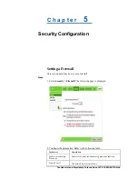
Page 50: ...his section describes how to set a firewall Steps 1 Select Security Firewall The following page is displayed 2 Configure the parameters Refer to the following table Parameter Description Enable Anti Hacking Protection Enables or disables the anti hacking protection function Firewall Level The firewall levels are as follows ...

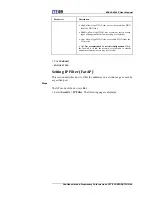
Page 51: ...ver Internet Low allows legal WAN side access and PING from the WAN side Off Not recommended to use this configuration When the firewall is closed the network is vulnerable to attacks and normal Internet access may be affected 3 Click Submit END OF STEPS Setting IP Filter Fat AP This section describes how to filter the addresses in a certain range or used by a specified port Steps The AP mode of t...

Page 52: ...r function Protocol The available options are ANY TCP User Datagram Protocol UDP TCP AND UDP and Internet Control Message Protocol ICMP ANY refers to any protocol Name Refers to the IP filter name The length is 1 to 256 characters Source IP Address Start IP address of the source LAN side End Source IP Address End IP address of the source LAN side Start Destination IP Start IP address of the destin...

Page 53: ...number of the end destination source LAN side address Ingress The availbable options are LAN IGD WD1 WCD1 WCIP1 or blank It is blank by default which refers to any mode Egress The availbable options are LAN IGD WD1 WCD1 WCIP1 or blank It is blank by default which refers to any mode Mode Select a filtering mode Discard or Permit Modify Click to modify the corresponding IP filter rule Delete Click t...

Page 54: ... Select a filtering mode Discard or Permit Type Specifies the type Bridge Route or Bridge Route Protocol Specifies the protocol IP Address Resolution Protocol ARP Reverse Address Resolution Protocol RARP PPPoE or ALL Source MAC Address MAC address of the device on the LAN side Destination MAC Address MAC address of the device on the WAN side Modify Click to modify the corresponding MAC filter rule...

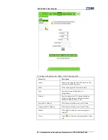
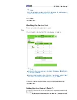
Page 55: ...ce ports Steps 1 Select Security Service List The following page is displayed Notes In the lists of services and ports Enable is 0 indicates Stop Enable is 1 indicates Start Under normal condition List of Service Connection recorded Client IP Address and AP device IP Address after log on HTTP 2 Check the detailed information about the service ports and connections END OF STEPS Setting Service Cont...

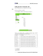
Page 56: ...ervice control function Ingress Supports LAN WAN or empty The default value is empty meaning any values Start Source IP Address Start IP address of the source End Source IP Address End IP address of the source Mode The options are Permit and Discard Service List The available options are Web File Transfer Protocol FTP and TELNET Select one or more options Modify Click to edit the corresponding acc...

Page 57: ...eter Description FTP ALG Open close the NAT conversion switch for the FTP protocol TFTP ALG Open close the NAT conversion switch for the TFTP protocol SIP ALG Open close the NAT conversion switch for the SIP protocol L2TP ALG Open close the NAT conversion switch for the L2TP protocol H323 ALG Open close the NAT conversion switch for the H323 protocol RTSP ALG Open close the NAT conversion switch f...

Page 58: ...function helps to discover various network devices automatically A devices supporting UPnP can access the network dynamically obtain the IP address and send its performance information If there are DHCP and DNS servers the device can obtain the DHCP and DNS services automatically A devices supporting UPnP can be disconnected from the network automatically without affecting the device itself or oth...

Page 59: ...vertisement Period in minutes Set the corresponding advertisement time as required The unit is minute Advertisement Time to Live in hops Set the corresponding time to live hop count as required 3 Click Submit END OF STEPS Setting a Device Name Fat AP This section describes how to set a device name Steps The AP mode of the device is Fat 1 Set the domain name i Select Application DNS Service Domain ...

Page 60: ...ete the corresponding host information END OF STEPS QoS Configuration Quality of Service QoS defines the quality agreement on the information transmission and sharing between network users For example the allowed transmission delay time the degree of distortion and the synchronization of audio and video The concept of Class of Service is introduced to QoS frame By using QoS ZXV10 W615 can complete...

Page 61: ...thm The available algorithms are SP DWRR and SP_DWRR SP Sends the group in a queue with higher priority in descending order of priorities When the queue with higher priority is empty the device will send the group in a queue with lower priority DWRR the priority cycle by weighting Each queue is served in turn SP_DWRR Adopts SP and DWRR The queue 0 adopts the SP algorithm The queue 1 to the queue 7...

Page 62: ...PORATION 3 Click Submit END OF STEPS Setting a Classification Rule This section describes how to set a classification rule Steps 1 Select Application QoS Classification The following page is displayed 2 Configure the parameters Refer to the following table Parameter Description ...

Page 63: ...ponding rule Delete Click to delete the corresponding rule Modify Click to modify the corresponding rule Delete Click to delete the corresponding rule Modify Click to modify the corresponding rule Delete Click to delete the corresponding rule DSCP Specifies the DSCP value of packets The value range is 0 to 63 Modify Click to modify the corresponding rule Delete Click to delete the corresponding ru...

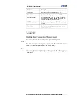
Page 64: ... not set A greater value indicates a higher priority DSCP Re marking Specifies the re marking value of DSCP The value range is 0 to 63 Queue Index Specifies the corresponding management queue number that ranges from 1 to 8 3 Click Submit END OF STEPS Configuring Congestion Management This section describes how to configure congestion management Context The default congestion management algorithm i...

Page 65: ...figuration function of QoS queues Queue Index Includes Queue 1 Queue 8 Queue 8 is enabled by default 3 Click the icon of the queue to be modified Select or clear the Enable check box 4 Click Modify END OF STEPS Configuring SNTP This section describes how to configure time management to achieve time synchronization with the time server Steps 1 Select Application SNTP The following page is displayed...

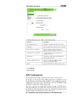
Page 66: ...ght Saving Time Enables or disables the daylight saving time function It is disabled by default DSCP Specifies the DSCP value The value range is 0 63 3 Click Submit END OF STEPS IGMP Configuration The multicast function allows sending the same data to several devices The IP host uses the Internet Group Management Protocol IGMP to report the qualifications of multicast group members to the neighbor...

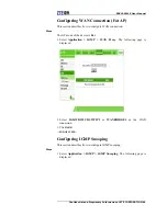
Page 67: ... connection Steps The AP mode of the device is Fat 1 Select Application IGMP WAN Proxy The following page is displayed 2 Select IGD WD1 WCD1 WCIP1 or WANBRIDGE1 as the WAN connection 3 Click Add END OF STEPS Configuring IGMP Snooping This section describes how to configure IGMP snooping Steps 1 Select Application IGMP IGMP Snooping The following page is displayed ...

Page 68: ...isabled by default Enable IGMP Snooping Enables or disables the IGMP snooping function It is enabled by default Enable IGMP Snooping Enhancement Enables or disables the IGMP snooping enhancement function It is enabled by default 3 Click Submit END OF STEPS Configuring MLD Snooping This section describes how to configure Multicast Listener Discovery MLD snooping Steps 1 Select Application MLD Snoop...

Page 69: ...Enable MLD Snooping and Enable MLD Snooping Enhancement Two parameters are all enabled by default 3 Click Submit END OF STEPS Configuring LED Control This section describes how to configure LED control Steps 1 Select Application LED Control The following page is displayed 2 Enable or disable the LED function 3 Click Submit END OF STEPS ...

Page 70: ...agement Steps 1 Select Administration SNMPv1 v2c The following page is displayed 2 Configure the parameters Refer to the following table Parameter Description Enable SNMP Enables or disables the SNMP function The default value is enabled Trap Server IP Enter the IP address of the Trap server for example 192 168 1 1 Trap Server2 IP Enter the IP address of the standby Trap server ...

Page 71: ...sword is public Write Community The default password is private 3 Click Submit END OF STEPS SNMPv3 Security Management USM Managing SNMPv3 Users This section describes how to manage SNMPv3 users Steps 1 Select Administration SNMPv3 Security USM SNMPv3 Users The following page is displayed 2 Configure the parameters Refer to the following table Parameter Description Security Name User name Authenti...

Page 72: ...3 user information Delete Click to delete the corresponding SNMPv3 user information 3 Click Add END OF STEPS Managing SNMPv1 v2c Users This section describes how to manage SNMPv1 v2c users Steps 1 Select Administration SNMPv3 Security USM SNMPv1 v2c Users The following page is displayed 2 Configure the parameters Refer to the following table Parameter Description Security Name User name Source IP ...

Page 73: ...ation 3 Click Add END OF STEPS SNMPv3 Access Control Management VACM Managing Context This section describes how to manage the context Steps 1 Select Administration SNMPv3 Access Control VACM Context The following page is displayed 2 Enter the context information The default is 3 Click Submit END OF STEPS Managing Security Groups This section describes how to manage security groups ...

Page 74: ...ecurity Model Supports USM SNMPv1 and SNMPv2c Security Name Supports nanpuser anpuser apuser Group Name Specifies the group name Modify Click to modify the corresponding security group information Delete Click to delete the corresponding security group information 3 Click Add END OF STEPS Managing View Subtree This section describes how to configure the view subtree Steps 1 Select Adminsitration S...

Page 75: ...ee name Mask Optional Subnet mask Type The options are included and excluded Modify Click to modify the corresponding view information Delete Click to delete the corresponding view information 3 Click Add END OF STEPS Managing the Access Table This section describes how to manage the access table Steps 1 Select Adminstration SNMPv3 Access Control VACM Access Table The following page is displayed ...

Page 76: ...refix Security Model Supports USM SNMPv1 SNMPv2c and any Security Level Supports noAuthNoPriv authNoPriv and authPriv Context Match The options are exact and prefix Read View Name The options are none and all Write View Name The options are none and all Notify View Name The options are none and all Modify Click to modify the corresponding access table information Delete Click to delete the corresp...

Page 77: ...onfigure the parameters Refer to the following table Parameter Description User Privilege Determines whether to modify the management maintenance account or common account Username The management maintenance account is admin and it cannot be modified The common account is user and it can be modified Old Password To modify the password of the management maintenance account enter the original login ...

Page 78: ...ministration User Management Auto Logout Management The following page is displayed 2 Set the timeout period within the range of 5 to 60 minutes The default is 5 minutes 3 Click Submit END OF STEPS Device Management Configuring System Management This section describes how to configure system management Steps 1 Select Administration System Management System Management The following page is displaye...

Page 79: ...Reboot for a warm restart of the device Click Cold Reboot for a cold restart of the device Click Restore Default to restore the factory settings END OF STEPS Setting Version Upgrade This section describes how to upgrade the ZXV10 W615 system through a Web page Steps 1 Select Administration User Management Software Upgrade The following page is displayed ...

Page 80: ... page To prevent the device from being damaged do not turn off the power or restart the device 2 Click Browse to select the desired software version file 3 Click Upgrade to upgrade the software version END OF STEPS Managing User Configuration This section describes how to manage user configuration Steps 1 Select Administration System Management User Configuration Management The following page is d...

Page 81: ...f the device To import a configuration file do as follow i Click Browse and select the configuration file to be imported ii Click Restore Configuration Then the specified configuration file is imported Notes The device automatically restarts after the operation is completed END OF STEPS Managing the Default Configuration This section describes how to manage the default configuration Steps 1 Select...

Page 82: ...ation file of the device To import the default configuration file do as follows i Click Browse and select the default configuration file to be imported ii Click Restore Configuration Then the specified default configuration file is imported Notes The device automatically restarts after the operation is completed END OF STEPS Configuring Log Management This section describes how to configure log ma...

Page 83: ... in ascending order After a log level is selected only logs of the selected level and with higher levels will be recorded Enable Remote Log Enables or disables the function of the remote login to the log server It is disabled by default Log Server Address Specifies the IP address of remote log server 3 Click the corresponding button as needed Click Refresh to view the latest log records Click Clea...

Page 84: ...t the AP mode Steps 1 Select Administration AP Management AP Mode The following page is displayed 2 Set the AP mode Fat or Fit based on the actual requirement Notes After the AP mode is changed the device restarts automatically 3 Click Submit END OF STEPS Setting an AP Name This section describes how to set an AP name Steps 1 Select Administration AP Management AP Name The following page is displa...

Page 85: ... the AP Name text box set the corresponding name 3 Click Submit END OF STEPS Diagnosis Configuration Performing Ping Diagnosis This section describes how to configure Ping diagnosis to detect device faults Steps 1 Select Administration Diagnosis Ping Diagnosis The following page is displayed ...

Page 86: ...t size text box type the suitable Ping packet size The value range is 1 4096 5 In Engress drop down box select the egress to be diagnosed Notes Engress supports LAN WAN and empty The default value is empty meaning any values 6 Click Submit The Ping result is displayed in the text box below END OF STEPS Configuring Trace Route Diagnosis Disconnected network nodes can be determined through Trace Rou...

Page 87: ... the IP Address or Host Name text box type the host IP address or host name 3 In the WAN Connection text box select the WAN connection to be diagnosed 4 In the Maximum Hops text box select the maximum number of hops to be diagnosed 5 In the Wait Time text box select the timeout period 6 Click Submit The Trace Route result is displayed in the area in the lower part END OF STEPS ...

Page 88: ...llation If this equipment does cause harmful interference to radio or television reception which can be determined by turning the equipment off and on the user is encouraged to try to correct the interference by one or more of the following measures Reorient or relocate the receiving antenna Increase the separation between the equipment and receiver Connect the equipment into an outlet on a circui...

Page 89: ...et Protocol version 4 IPv6 Internet Protocol Version 6 ISP Internet Service Provider MAC Medium Access Control Message Authentication Code MTU Maximum Transfer Unit Multi Tenant Unit Maximum Transmission Unit NAT Network Address Translation NTP Network Time Protocol PoE Power over Ethernet QoS Quality of Service RARP Reverse Address Resolution Protocol SNMP Simple Network Management Protocol STP S...

Reviews: