ZXR10 8900E series Core Switch Product Description
ZTE Confidential Proprietary
© 2013 ZTE CORPORATION. All rights reserved.
59
In MPLS TE network usually MPLS TE FRR is deployed, which is determined by MPLS
TE’s features. In pure IP network, when there’s partial failure, if there are other available
route to the same destination, packets will be forwarded along these routes. Before route
change caused by the failure spreads to the whole network, only this mechanism can
quickly implement partial failure protection. In MPLS network with no TE deployed, LDP
setting up LSP by DU is widely applied. When partial failure occurs, if there are other
available routes, LDP will initiate LSP creation to upstream nodes. Not considering TE
related needs such as bandwidth, priority and link attribute, the possibility of successfully
creating LSP is comparatively big. Thus the process from failure to recovery is short. In
MPLS TE network, LSPs are usually established in DoD mode through RSVP. On a head
end, the CSPF algorithm calculates a path based on the routing information of the area
that satisfies the constraints and RSVP establishes an LSP along the path. When an
element along the LSP fails, a new LSP needs to be established. However, CSPF cannot
calculate the path before the head end knows the route change. In addition, a partial
failure may make it necessary to reestablish multiple LSPs. During LSP reestablishment,
problems such as insufficient bandwidth may intervene. Therefore, compared with pure
IP network and MPLS network with no TE configured, MPLS TE network needs more
time to recover from partial failure. So one standby LSP is set up in advance in MPLS TE
network. Initiating FRR and quick switching can be implemented in partial network failure.
3.7.7.4
L3VPN FRR
L3VPN FRR is used to solve CE dual-homing, which is the most common end-to-end
service convergence problem for network model. It can control end-to-end service
convergence within 1s in case of PE node failure. Since MPLS TE FRR can only solve
link or node failure between PE, and PE needs to rely on VPN route convergence when it
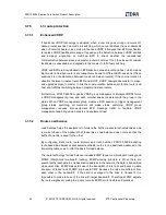
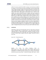
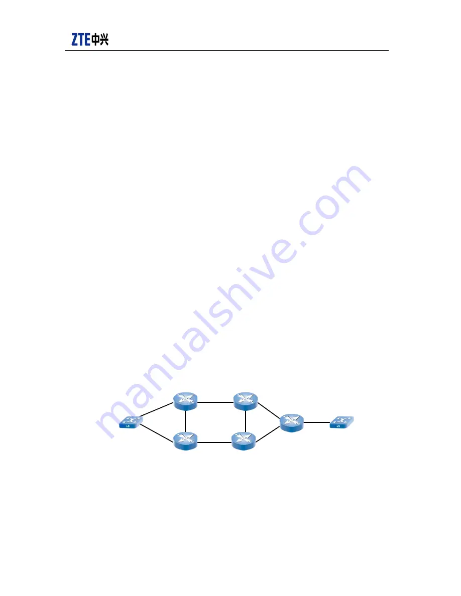
has failure, end-to-end fast convergence cannot be realized. CE model is shown in
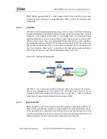
Figure 3-26:
Figure 3-26 CE dual-homing model
Suppose the path for CE-B accessing CE-A is:
CE-B——PE-E——P-C——PE-A——CE-A. When PE-A node fails, the path for CE-B
accessing CE-A is converged as: CE-B——PE-E——P-D——PE-B——CE-A. Based on
standard MPLS L3 VPN, PE-A and PE-B both distribute route directing to CE-A to PE-E,
and distribute private network labels. In traditional technology, PE-E selects a VPNV4
CE-A
CE-B
PE-A
PE-B
PE-C
PE-D
PE-E
Summary of Contents for ZXR10 8900E series
Page 1: ...Operator Logo ZXR10 8900E series Core Switch Product Description ...
Page 2: ......
Page 10: ......

