

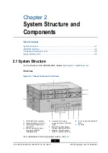

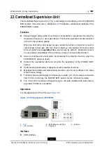


Chapter 2 System Structure and Components
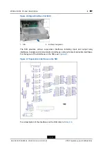
Table 2-6 Supervision Interfaces on the SIB
Interface
Description
Input and Output Relay Interfaces
X3
In-relay 1, 2
X4
In-relay 3, 4
Four input relays.
The users can set the alarms for the input relays in the
Centralized Supervision Unit (
).
Out-relay 1
Alarm code A1: critical or major alarm
X14
Out-relay 2
Alarm code A2: door alarm
Out-relay 3
Alarm code A3: AC power abnormal
X15
Out-relay 4
Alarm code A4: ambient temperature high
Out-relay 5
Alarm code A5: minor alarm or warning
X16
Out-relay 6
Alarm code A6: __________________________
Reserved for user definition.
Out-relay 7
Alarm code A7: __________________________
Reserved for user definition.
X17
Out-relay 8
Alarm code A8: __________________________
Reserved for user definition.
X18
CSU fault out-relay
Provides the CSU fault signal
Background Communication Interfaces
X11
RS232 communication
X11 and X13 cannot be used at the same time
X12
RS485 communication
(independent)
-
X13
RS485 communication
(multiplex)
X11 and X13 cannot be used at the same time
X22
RS232 communication
Multiplex with X11
Environment Detection Interfaces
X2
Flood alarm
To connect a flood sensor
X5
Door magnet alarm
To connect a door sensor
X6
Battery 1 temperature
To connect the temperature sensor for battery pack 1
X7
Battery 2 temperature
To connect the temperature sensor for battery pack 2
X8
Battery 3 temperature
To connect the temperature sensor for battery pack 3
X9
Battery 4 temperature
To connect the temperature sensor for battery pack 4
X10
Environment temperature
To connect an ambient temperature sensor
2-9
SJ-20120703093141-002|2013-01-08 (R1.2)
ZTE Proprietary and Confidential


