background image


25    

Configuring the BIOS
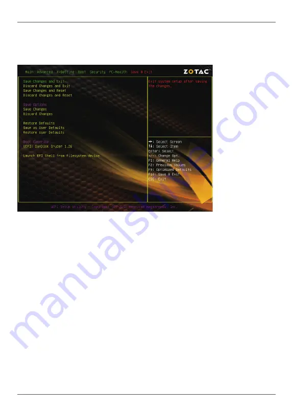
Exit Menu


The exit menu items allow you to load the option or failsafe default values for the BIOS 

items, and save or discard your changes to the BIOS items. Press <enter> to display 

the sub-menu:

Save Changes and Exit

Select this item and press <Enter> to save the changes that you have made in the 

BIOS Setup and exit the BIOS Setup. When the diolog box [Save configuration and 
exit?] appears, select [Yes] to save and exit, or select [No] to return to the main menu.

Discard Changes and Exit

Select this option only if you do not want to save the changes that you have made 

to the setup program. If you made changes to fields other than system date, system 

time, and password, the BIOS asks for a confirmation before exiting.

Save Changes and Reset

Select this item and press <Enter> to reset the system after saving the changes. 

When the diolog box [Save configuration and reset?] appears, select [Yes] to save 

and reset, or select [No] to return to the main menu.

Discard Changes and Reset

Select this item and press <Enter> to reset system setup without saving any changes. 

When  the  diolog  box  [Reset  without  saving?]  appears,  select  [Yes]  to  discard  and 

reset, or select [No] to return to the main menu.

Summary of Contents for Intel NM70-ITX Series

Page 1: ......

Page 2: ...R OR AN EXPERIENCED AUDIO TELEVISION TECHNICIAN NOTE Connecting this device to peripheral devices that do not comply with Class B requirements or using an unshielded peripheral data cable could also r...

Page 3: ...SPDIF Out Header CN5 12 COM Header CN3 12 Front Panel Header FP1 12 USB Headers FP_U1 2 13 Front Pannel Audio Header FP_S1 13 Speaker Header SPK1 14 Serial ATA SATA Connectors SATA1 3 14 Fan Connecto...

Page 4: ...Discard Changes 26 Restore Defaults 26 Save as User Defaults 26 Restore User Defaults 26 Launch EFI Shell from filesystem device 26 Flash Update Procedure 26 Installing Drivers and Software 27 Driver...

Page 5: ...he back panel four via internal pin headers v Supports USB 2 0 protocol up to 480 Mbps transmission rate q USB 3 0 ports v Supports hot plug and play v Two USB 3 0 ports on the back panel v Backwards...

Page 6: ...5 Motherboard Specifications q Graphics Features v VGA HDMI outputs v Support up to 2560x1600 resolution q Expansion slots v One PCI slot...

Page 7: ...rd Layout 1 24 pinATX Power Connector PW1 2 Serial ATA SATA Connectors SATA2 3 3 Front Panel Header FP1 4 Speaker Header SPK1 5 SATADOM SATA disk Module Connector SATA1 6 Clear CMOS Jumper JP1 7 Chips...

Page 8: ...ED indicators Speed LED Status Description Off Speed 10 Mbps Green Speed 100 Mbps Orange Speed 1000 Mbps Speed LED Activity LED 1 PS2 Keyboard Port 2 Clear CMOS Button 3 HDMI Port 4 VGA Port 5 USB 3 0...

Page 9: ...240 121 120 240 121 1 5V 1 5V DDRIII1 DDRIII2 Installing Memory Modules Your new motherboard has two 1 5V 240 pin slots for DDR3 memory These slots support 1 GB 2 GB 4 GB 8 GB DDR3 devices There must...

Page 10: ...and promotes correct airflow within the chassis Before installing the motherboard install the I O shield from the inside of the chassis Press the I O shield into place and make sure it fits securely...

Page 11: ...r Connector PW1 v 4 pin ATX_12V Power Connector PWR2 q Internal Headers Connectors v SPDIF Out Header CN5 v COM Header CN3 v Front Panel Header FP1 v USB 2 0 Headers FP_U1 2 v Front Pannel Audio Heade...

Page 12: ...V 18 GND 7 GND 19 GND 8 PWROK 20 5V 9 5V_AUX 21 5V 10 12V 22 5V 11 12V 23 5V 12 3 3V 24 GND 4 pin ATX_12V Power Connector PWR2 PWR2 the 4 pin ATX 12V power connector is used to provide power to the CP...

Page 13: ...e indicator LED cable to these two pins The HDD indicator LED indicates the activity status of the hard disks q RST SW Attach the Reset switch cable from the front panel of the case to these two pins...

Page 14: ...t audio connector Also please make sure the pin assignment on the cable is the same as the pin assignment on the mainboard header To find out if the chassis you are buying supports a front audio conne...

Page 15: ...ximum transfer rate up to 3 0 Gb s each and one SATA III port SATA1 has power pin 5V GND with maximum tranansfer rate up to 6 0 Gb s each SPK1 Pin Definition PIN Assignment 1 VCC 2 NC 3 NC 4 SPK SATA...

Page 16: ...PCI Slot PCI1 The PCI slot supports cards such as a LAN card USB card SCSI card and other cards that comply with PCI specifications Expansion Slots The motherboard contains one PCI slot 120 240 121 12...

Page 17: ...to clear the system configuration use the JP1 Clear CMOS Jumper to clear data Notice 1 Be sure to save the CMOS setting when exit the CMOS 2 If the CPU is frequency multiplier locked no CPU speed cha...

Page 18: ...ys at the bottom of the screen during the Power On Self Test POST Pressing Del takes you to the BIOS Setup Utility Note 1 We reserve the right to update the BIOS version presented in the manual The BI...

Page 19: ...etting for the CPU and other system devices Press enter to display the configuration options ACPI Configuration The items in this menu allow you to set or change the ACPI configurations Press enter to...

Page 20: ...Selection Allows you to choose SATA mode including IDE Mode AHCI Mode and RAID Mode PCH FW Configuration The items in this menu allow you to set or change the PCH FW configurations Press enter to dis...

Page 21: ...configure how the system board responds to a power failure q Wake Up by USB KB Mouse from S3 Enable or disable wake up by USB PS2 KB Mouse from S3 q Wake Up by PS2 KB Mouse from S3 S4 S5 Enable or di...

Page 22: ...is menu allows you to set network stack q Network stack This item allows you to enable or disable UEFI network stack X Setting Menu The X Setting menu items show the settings of CPU memory and so on P...

Page 23: ...guration options q Setup Prompt Timeout This item shows the number of seconds to wait for setup activation key q Bootup NumLock State Use this item to select the keyboard NumLock state On or Off q Qui...

Page 24: ...ty menu items allow you to change the system security settings Press enter to display the configuration options q Administrator Password Select this item to set Setup Administrator Password q User Pas...

Page 25: ...isable smart fan function q System CPU Fan Mode Use this item to select system CPU fan mode q System CPU Fan Start Temperature Use this item to select the system CPU fan start temperature q System CPU...

Page 26: ...nd Exit Select this option only if you do not want to save the changes that you have made to the setup program If you made changes to fields other than system date system time and password the BIOS as...

Page 27: ...uthorized Service Center and have a trained technician do the work for you Save Changes Select this item and press Enter to save the changes that you have made in the BIOS Setup and exit the BIOS Setu...

Page 28: ...s section are for reference only The kit comes with a driver disk that contains utility drivers and additional software The driver disk that has been shipped with your motherboard contains the followi...

Page 29: ...28 Intel NM70 ITX series Motherboard 2 Left click Intel Chipset Driver begin loading 3 Left click HDA Sound Driver begin loading...

Page 30: ...29 Installing Drivers And Software 4 Left click Intel Graphics Driver begin loading...

Page 31: ...30 Intel NM70 ITX series Motherboard 5 Left click Ethernet PCI E Driver begin loading...

Page 32: ...31 Installing Drivers And Software 6 Left click USB3 0 Controller Driver begin loading 7 Left click Intel Management Engine begin loading...

Page 33: ...32 Intel NM70 ITX series Motherboard 8 Left click Intel R Rapid Storage Technology begin loading...

Page 34: ...33 Installing Drivers And Software...

Page 35: ...iver dsk and follow the on screen instructions Realtek HD Audio Manager icon will show in System tray as below Double click the icon and the control panel will appear Digital Output After clicking on...

Page 36: ...row in Others you will find more optimized settings available to you Karaoke Mode Karaoke mode brings Karaoke fun back home by simply using the music you usually play Karaoke mode can help you elimina...

Page 37: ...es you from default speaker settings Speakers includes four tabs Speaker Configuration Sound Effects Room Correction and Default Format Speaker Configuration In this tab you can choose speaker configu...

Page 38: ...uppress disturbing noise Acoustic Echo Cancellation This function prevents playback sound from being recorded by microphone together with your sound For example you might have chance to use VOIP funct...

Page 39: ...udio Manager integrates Volume Control functions into the Line In page This gives you the advantage to you to create your favorite sound effect in one single tool Single click on the volume icon the R...

Page 40: ...of Realtek HD Audio Manager page and you can set the playback device and recording device as below Connector Settings Click on the icon on the main page of Realtek HD Audio Manager and the Connector...

Page 41: ...er of Realtek HD Audio Manager page the Realtek HD Audio information will display Hardware Software information of your audio system Language setting When Audio is chosen this language setting would a...

Page 42: ......

Reviews: