R4 is a 2k trimpot who can provide and alternative gain for the whole stage: boost1
and boost2 are connected to an external footswitch which will connect or disconnect
the trimpot in parallel with R5. Thus changing the equivalent resistance value
according to R5 position: (R4*R5)/(R4+R5). So the equivalent resistance could be
trimmed from 0 if R5=0 oHms. Down to 666 oHms.
I personally set it up around 1k to get a 2x gain when engaging R5.
But this gain stage works together with the clipping stage. R8 limits the output
current when the clipping mode is set to hard.
Clippers stage:
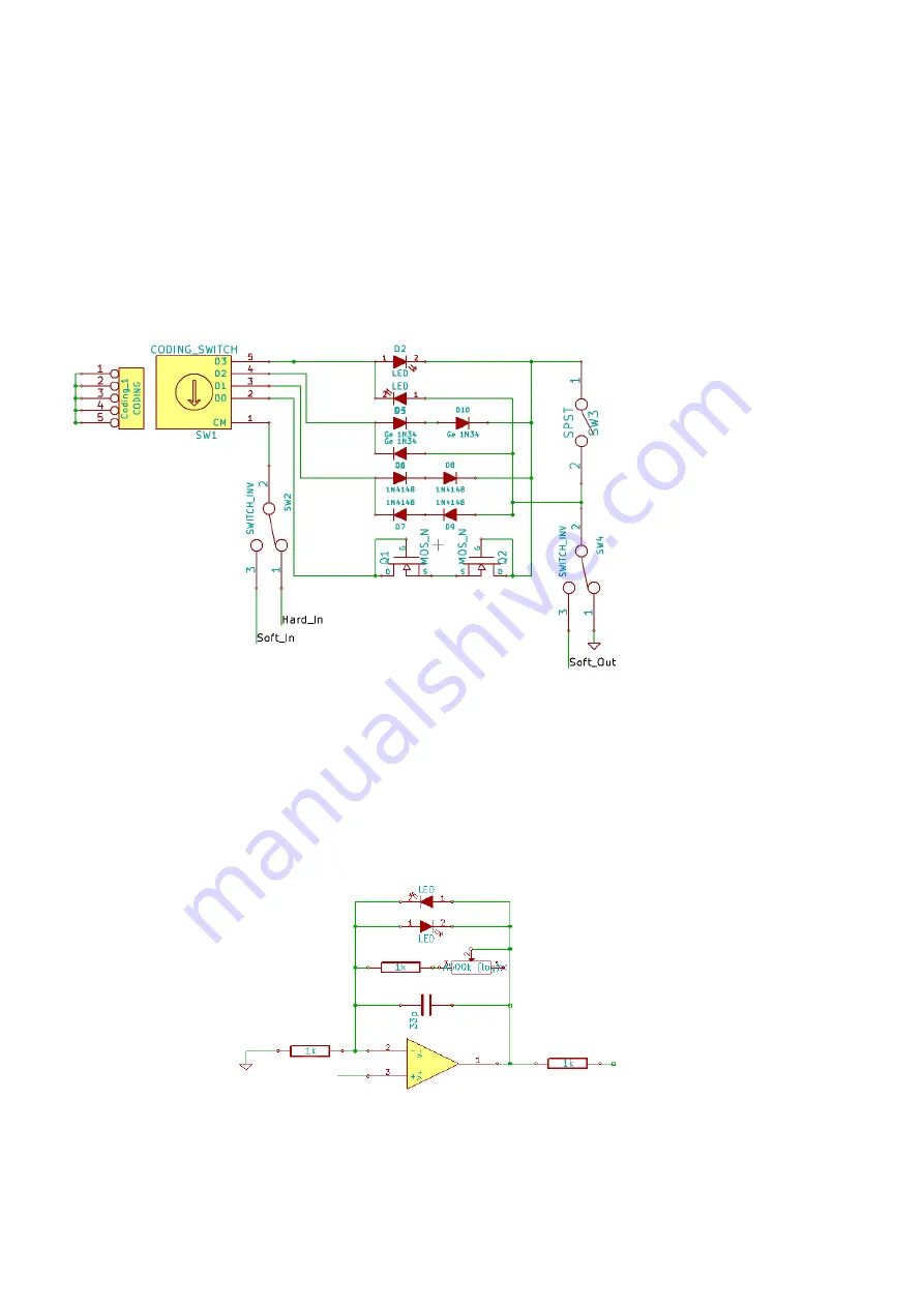
The clipping stage provides the choice between 4 different clippers. For each
clippers there's the possibility to use symmetrical or asymmetrical clipping and hard
or soft clipping. So there are 2*2*4 = 16 combinations available.
Switches SW2 and SW4 are actually the same DPDT on/on switch.
They either connect the clippers in the feedback loop of the op-amp either at the
output.
When connecting to the feedback loop, we have the following schematic:
Leds will provides smooth clipping distortion. Being green leds, if the output of the
opamp rise higher than their threshold (+/-2V), they will short circuit the GAIN pot
and 1k resistance, but as soon as the gain pot is short circuited the gain of the
Copyright Zorg Effects G.Denneulin december 2015 – For non commercial use only.
5


