background image

20

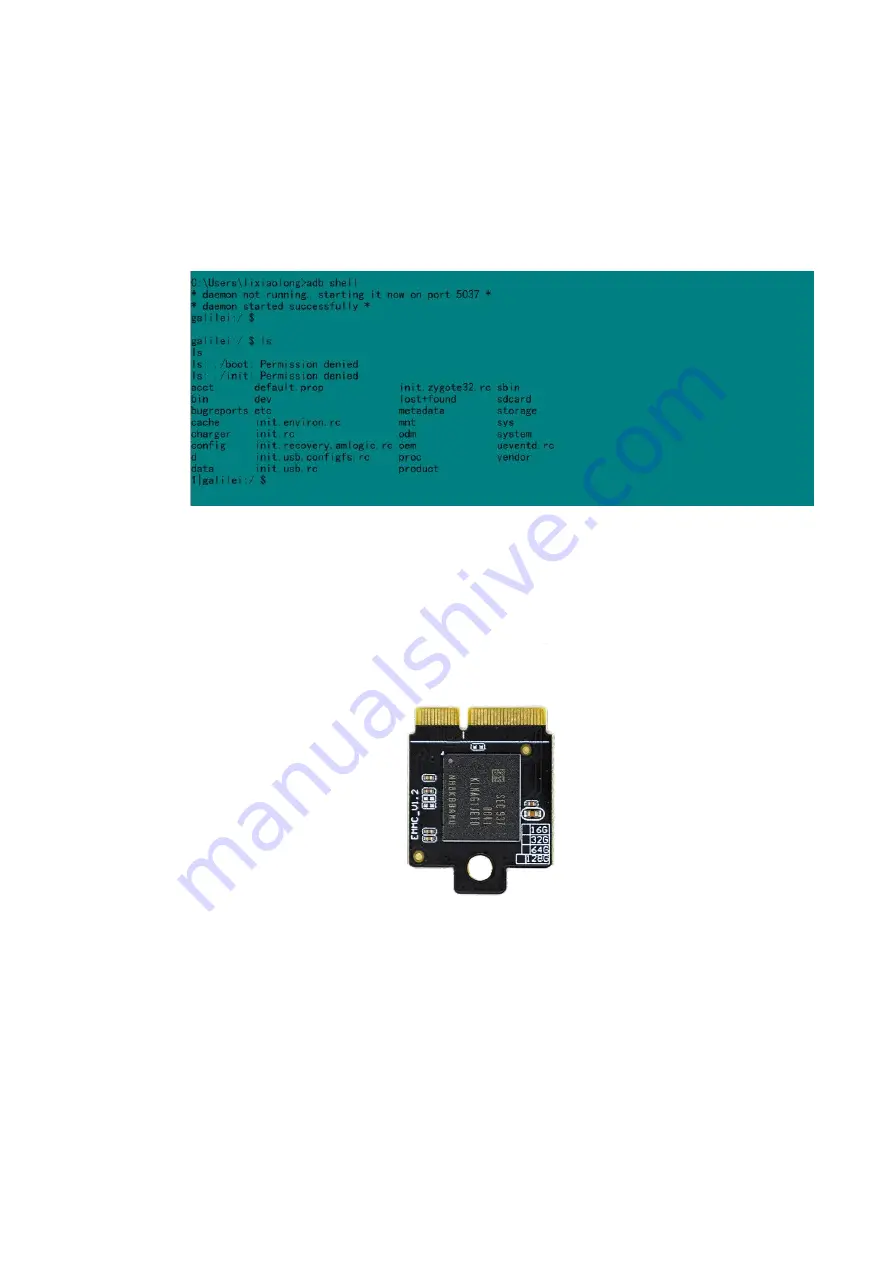
5. Set ADB debugging

5.1 Android operating system on

a. The development board supports ADB debugging by default ,Connect directly
through OTG interface。Before connect otg ,make sure the computer has an ADB
driver installed。
b. Open terminal window and type in adb shell

6. EMMC extension module instructions

6.1 EMMC EMMC pluggable expansion module , Capacity of hard disk is 8GB

(Customizable capacity 16GB,32GB,64GB)

6.2 EMMC module Dimension drawing

Summary of Contents for P1

Page 1: ...1 Zora P1 DEVELOPMENT BOARD Zora P1 V1 0 電波法により5GHz帯は屋内使用に限ります ...

Page 2: ...se hardware interface uart debug enter burning mode 9 2 3 Use ADB tool to enter burning mode 10 3 Detailed method and operation steps of disassembling and burning firmware 11 3 1 Configuration requirements for computers 11 3 2 Using the update button to burn the firmware 11 3 4 Use hardware interface uart debug enter burning mode 16 3 5 Burn firmware with ADB tool 17 3 6 Burn the firmware to multi...

Page 3: ...P1 A311D 4G 01 Introduction of Development Board Interface 1 1 Front picture of development board 1 2 Back picture of development board 1 3 Introduction to hardware interface processor Amlogic Quad A73 Dual A53 ...

Page 4: ...2x2 MIMO BT5 0 10m Ethernet RJ45 GigE Vision POE Pin Extra Cap Microphone On board PDM PDM interface microphone Debug Micro USB Buttons Power Reset ADC Update and act OPEX Wifi LED Power status indicator 42Pin GPIO Detail in 42Pin GPIO introduction UART 1 I2C 2 SPI 2 I2S 1 PWM 2 ADC 1 DC OUT 1x5V 1x3 3V GPIO 8 Ground 8 PMU YK613 DC IN 12V 2 1mm OS Android 9 Ubuntu 18 04 Linux 4 9 Replace firmware ...

Page 5: ...IO2 GPIO3 GPIO4 GND PWM2 5V 5V SDA SCL SDA2 SCL2 GND P_D1 P_D0 P_SY P_CK GND GCLK 32K GND GPIO5 GPIO6 GPIO7 GPIO8 GND PWM1 3 3V 3 3V 42 1 5 Uart introduction from 01 to 04 3 3V 01 RX TX GND 04 1 6 PMD introduction from 01 to 04 3 3v 01 3 3v GND PDM_DCK GND PDM_DIN0 PDM_DIN1 GND 07 1 7 RTC introduction GND 01 VBAT 02 ...

Page 6: ...6 1 8 Product size description 116 100mm ...

Page 7: ...7 2 Preparation for firmware burning There are three ways to enter burn mode 2 1 Long press update button enter burn mode a Long press update button ...

Page 8: ...8 b Connect the OTG interface of development board through windows win 10 or win7 system computer ...

Page 9: ...e interface uart debug enter burning mode a Using USB to UART serial port tool connect the UART debug interface b Through serial protocol tool software type in reboot c When the development board is restarted Press enter continuously and ente uboot mode d type in update e Successfully linked the burning software ...

Page 10: ... Power on the development board by connecting the power adapter b Open the computer CMD console c Connecting computer and development board with the otg interface d CMD console type in adb reboot update e Successfully linked the burning software ...

Page 11: ...uters a Windows 7 or windows 10 operating system b Turn off antivirus software c has a high speed USB 2 0 or USB 3 0 interface 3 2 Using the update button to burn the firmware a Long press the update button development board b Using micro USB cable to connect OTG hardware interface c Open the software USB burning 2 2 X ...

Page 12: ...12 c 1 software interface English d Supply power to development board through power supply adaptation e Burning tool successfully connected to development board ...

Page 13: ...13 e 2 Software interface English f Import firmware x img ...

Page 14: ...14 f 2 Software interface English g Click the start button enter burning state ...

Page 15: ...15 g 2 Software interface English h Complete firmware burning ...

Page 16: ...t debug enter burning mode a Using USB to UART serial port tool connect the UART debug interface b Through serial protocol tool software type in reboot c When the development board is restarted Press enter continuously and ente uboot mode d Type in update e Burning tool successfully connected to development board ...

Page 17: ...e Start button then waiting for burning h Complete firmware burning i Click the stop button close the tools 3 5 Burn firmware with ADB tool a Power on the development board by connecting the power adapter b Open the computer CMD console ...

Page 18: ...g interface d CMD console type in adb reboot update e Successfully linked the burning software f Import the burning firmware g Click the start button then waiting for burning h Buring the firmware successful i Click the stop button and close the Burning tools ...

Page 19: ...ware to multiple development boards at the same time 1 Using USB hub with power supply 2 Use the same operation as step 3 2 3 Support two or more development boards to be burned at the same time 3 7 Download burning tools ...

Page 20: ...directly through OTG interface Before connect otg make sure the computer has an ADB driver installed b Open terminal window and type in adb shell 6 EMMC extension module instructions 6 1 EMMC EMMC pluggable expansion module Capacity of hard disk is 8GB Customizable capacity 16GB 32GB 64GB 6 2 EMMC module Dimension drawing ...

Page 21: ... 6 3 Picture of the EMMC module installed Fixed by copper post 7 POE Module introduction 7 1 POE Module support IEEE 802 3at standard and compatible IEEE 802 3at standard 7 2 POE module Dimension drawing ...

Page 22: ...tion of the equipment connected to the development board and the normal GPIO voltage output normal network bandwidth Please select a router or switch that supports both gigabit network card and ieee802 3at standard c Connect Poe module through LAN port of switch or router Just use the ordinary Ethernet cable d It can work normally when the development board is not connected to the power and networ...

Page 23: ...ency energy and if not installed and used in accordance with the instructions may cause harmful interference to radio communications However there is no guarantee that interference will not occur in a particular installation If this equipment does cause harmful interferenceto radio or television reception which can be determined by turning the equipment off and on the user is encouraged to try to ...

Page 24: ...24 9 Hardware data of development board 9 1 Schematic diagram ...

Page 25: ...25 9 2 Hardware design drawing a Front of plate and frame drawing b bakc of plate and frame drawing ...

Page 26: ... 9 3 Chipset datasheet A311D Datasheet 05 pdf 10 Firmware Download 10 1 Android firmware a orbbec_pi_p2_android_v1 0_20200306 img md5 10 2 Ubuntu firmware a orbbec_pi_p2_ubuntu_18 04_v1 0_20200306 img md5 ...

Page 27: ... list of parts NO Name Quantity top board 1 floor 1 lift board 1 right board 1 front board 1 back board 1 SOO 4 eMMC rivet 1 case screw 4 case nut 4 11 1 2 Installation procedure Step Diagrams State 1 Put the floor and place it on the plane in the direction shown in the diagram ...

Page 28: ... into the floor in the direction as shown in the diagram the inserting mechanism between the plates is interference fit and it is normal to install the plates loosely in this step 3 Place the development board into the shell as shown ...

Page 29: ...positioning holes of the development plates according to the position indicated by the arrow line and then screw into the four nuts fixed on the bottom plate and tighten them 5 Install the top board in the direction shown in the diagram ...

Page 30: ...the figure and tighten them 7 Finish 11 1 3 Other description If you need to install and deploy other development board accessories or peripherals on the housing such as the eMMC memory card fan for the Obi MID Light 3D camera etc please refer to the installation instructions for the corresponding accessories 11 2 The power adapter 11 3 RTC 11 4 Touch module and LCD display 11 5 Microphone array F...

Reviews: