background image

1.0 Introduction 

 
The A1575 Premier AL Repeater (

REP AL

) range of repeaters is designed for use with the Premier AL 

Panel.  Three versions are available for each panel: - 
 
1)


The Basic LCD display Repeater with user controls (Please refer to the section on user controls for 
a full specification). It is powered from the panel and comes in a smaller cabinet size as shown in 
the Cabinet Specifications. 

 
2)


The repeater complete with power supply, in the smaller enclosure as above. 

 
3)


The repeater complete with zone LEDs and space for optional printer.  This unit is housed in the 
larger cabinet detailed in the Cabinet Specifications. 

 
The display with the data cable terminations is fitted to the removable door.  The power supply option is 
fitted to a detachable chassis, thus facilitating a completely empty enclosure for first fix installation.  Top 
entry plastic grommets, bottom/rear entry plastic grommets (for mains) and rear entry knockouts are 
designed to assist with cable installation. 
 
The repeater has a 4 line x 20 character backlit LCD display, showing device address, zone, type, status and 
location text. The user controls are accessed by means of keyswitch enabled membrane controls.  
 
Up to 14 repeater panels can be connected to the RS 485 repeater terminals. The basic repeater can be 
powered either from the panel’s auxiliary supply (See Battery and Loop calculator for maximum values) or 
from a local power supply. 
 
Only One Repeater can be powered from the Premier AL Aux Power Rail. ( 28v 0v). Any additional 
Repeater will need a separate power source, unless a power supply is fitted in the Unit.


Summary of Contents for ZT37 -250 REP-AL/P

Page 1: ...Small Repeater Semi Flush Bezel 4 2 3 Small Repeater Fully Flush Bezels 5 3 0 Hardware Specifications 6 3 1 User Controls Indications General Overview 7 3 2 Printed Circuit Board Viewed from Inside the Cabinet 9 4 0 Cabinet Installation 9 5 0 Display Address Setting 11 6 0 Commissioning Procedure 11 Appendices 14 i Technical Specifications 14 ii Other Relevant Documentation 14 iii Repeater Node DI...

Page 2: ...e door The power supply option is fitted to a detachable chassis thus facilitating a completely empty enclosure for first fix installation Top entry plastic grommets bottom rear entry plastic grommets for mains and rear entry knockouts are designed to assist with cable installation The repeater has a 4 line x 20 character backlit LCD display showing device address zone type status and location tex...

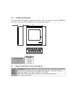
Page 3: ...et options Dimensions Protection Plugs 13 off a 370mm b 325mm c 106mm 2 1 Repeater Panel Order Codes Descriptions Part No Description 2500 830 Premier AL LCD repeater panel powered from main panel Size 370h x 325w x 100d 2500 842 Premier AL repeater c w 1A psu Size 370h x 325w x 100d 2500 844 Premier AL LCD repeater with zone LEDs c w 1A psu and space for printer Size 480h x 410w x 140d b c a ...

Page 4: ... 330mm Hole depth c 76mm Max bezel height d 435mm Max bezel width e 388mm Bezel overlap f 30mm Bezel depth g 30mm Door protrusion h 30mm Part No Description 2501 121 Semi flush bezel to fit A1575 Small Repeater 2501 124 Semi flush bezel to fit A1575 large Repeater a b d h c e f g ...

Page 5: ...pecification 2501 128 Fully flush stainless steel bezel for A1575 small repeater panel brushed or polished 2501 129 Fully flush brass bezel for A1575 small repeater panel brushed or polished 2501 153 Fully flush painted bezel for A1575 large repeater panel painted to customer s specification 2501 154 Fully flush stainless steel bezel for A1575 large repeater panel brushed or polished 2501 155 Full...

Page 6: ...ay board assembly mounted on removable door Battery Clamps Optional Power Supply Mounted on Chassis Display board and zone LED assembly mounted on removable door Optional Printer Battery Clamps Power Supply mounted on removable chassis ...

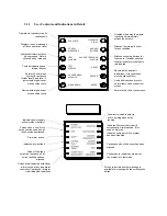
Page 7: ... 30 27 28 29 12 11 13 15 14 16 CONTROLS ACCESS 6 5 4 3 2 1 Switch to 1 to enable controls enter level 2 Override delay operates with switch in either position User controls Only override delay is available without operating the access controls keyswitch User indications 20 character by 4 line LCD display Back lit when event present or Access controls switch ON Zonal fire red and fault yellow indic...

Page 8: ...re conditions must be silenced first Tests all indications and internal buzzer Used within access menu to delete items and escape from menus Enters text in the access menus Operates all sounder circuits continuously Displays the next message at the current event level Activates all alarm outputs when pressed Alarms silenced when released Enters the user menu system for access to further level 2 an...

Page 9: ...When changing any plug in cards or printers observe anti static precautions Ensure that all power is removed from the system Failure to do so may result in damage to the cards or panel The panel must be located in a clean dry position which is not subject to shock or vibration and at least 2 metres away from pager systems or any other radio transmitting equipment The maximum temperature range is 0...

Page 10: ...ations DANGER Do not incinerate batteries If placed in a fire the batteries may rupture with the potential to release hazardous gases and electrolyte VRLA batteries contain substances harmful to the environment Exhausted batteries must be recycled Return them to the battery manufacturer or take them to your Council tip for appropriate disposal The versions of this repeater panel fitted with a powe...

Page 11: ...e node address DIL switch 6 0 Commissioning Procedure 1 If a power supply unit is fitted then gland a 230 VAC mains supply into the enclosure and attach the cables to the mains terminal block DO NOT SWITCH THE MAINS POWER ON AT THIS TIME 2 Set the node address DIL switch on the A1575 board to the required display number as shown in Appendix iii Each repeater must be addressed sequentially without ...

Page 12: ...w only the time and fire alarm panel name The same should be displayed at the main fire alarm panel 12 Press and hold the TEST DISPLAY button on the repeater Check that all the LEDs on the repeater illuminate the LCD backlight illuminates the LCD shows all the pixels as black the buzzer sounds and the zonal LEDs illuminate if fitted Release the button to return the display to normal 13 If a local ...

Page 13: ...If you are installing more than one A1575 repeater then each repeater should be installed and commissioned individually ...

Page 14: ...n battery current with one board 80mA 145mA Maximum battery current with zone board 180mA 245mA With printer Mains failed battery current with printer 45mA 110mA Alarm condition battery current with one board 80mA 145mA Maximum battery current with printer 420mA 485mA With printer and zone board Mains failed battery with zone board and printer 45mA 110mA Alarm condition battery current with one bo...

Page 15: ...used 1 ON OFF OFF OFF Repeater 1 2 OFF ON OFF OFF Repeater 2 3 ON ON OFF OFF Repeater 3 4 OFF OFF ON OFF Repeater 4 5 ON OFF ON OFF Repeater 5 6 OFF ON ON OFF Repeater 6 7 ON ON ON OFF Repeater 7 8 OFF OFF OFF ON Repeater 8 9 ON OFF OFF ON Repeater 9 10 OFF ON OFF ON Repeater 10 11 ON ON OFF ON Repeater 11 12 OFF OFF ON ON Repeater 12 13 ON OFF ON ON Repeater 13 14 OFF ON ON ON Repeater 14 15 ON O...

Reviews: