Zoning Zity Installation And Service Manual Download Page 14

ϭϰ


sϴ͘Ϯϭ


/ŶƐƚĂůůĂƟŽŶDĂŶƵĂů


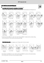
3 Learning and start-up 

In  the  first  place,  it  is  necessary  to  carry  out  the  appraisal 
process  in  order  to  detect  all  the  system's  elements  and 
start-up can be carried out later (once recognised). 

Place the switches according to the type of the system (Direct 
expansion, Fancoil, Boiler…). See page 11 


Make sure that DIP 8 is OFF (up). 

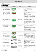
3.2 Exiting learning modeSalir del modo aprendizaje 


1 Wait for 30 seconds after the last component has been 
detected. 
2 Pull down the DIP8 (ON). 
3 Disconnect the voltage to the ZITY  

control unit. 

3.4   Learning  and start-up for systems with zone expansion modules 


The learning process should be carried out at the same 
time in all the control units, main board (ZITY-RC or ZITY- W) 
and expansion modules (ZITY-W/ME). 


The SW1 DIP 8 should therefore be placed in learning 
mode for all units (central and modules). 

The LEDs for the associated zones will be enabled in each 
control unit. The main board will detect, apart from the 
zones, the expansion modules (LED R2 or LED R2/R3, 
OFF). 
* For RC systems, enter the ID for the main board in all 
thermostats.  

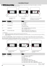
3.1   Recognising components   

1.  Connect the 230VAC power supply 

of the ZITY control unit. 

2.  The control unit is positioned  in     

learning mode and the 7 LEDs  
corresponding  to  the relays begin 
to flash. 

3.  Every time the thermostat of one of 

the zones is recognized by the   
control unit, the LED for the zone 
lights up in green. 

The upper row of LEDs 
corresponds to       
peripheral detection. 
Each time one of them 
is detected, the      
associated LED goes 
out.  


LED R1: Pasarela de comunicación máquina.  
LED R2: Modulo de expansión 7-12 zonas 
LED R3: Modulo de expansión 7-12 zonas 
LED R4: Central combinada W-MC 
LED R5: Central Slave 1 
LED R6: Central Slave 2 
LED R7: Central Slave 3 

3.3 Start-up in normal operating mode  

1 Connect the ZITY control unit again. 
2 When power is supplied to the control unit, it will begin 
  to operate normally according to the settings specified 
  in the SW1. 

3.5   Learning  and  start-up  for systems with  combined  modules  (…-MC

). The learning process must be carried out on both 

boards (the main one and the combined one), with the following particularities; 

3.5.1  ZITY-RC/MC  Combined  modules:  First,  check  that  both 
the  base  board  (ZITY-RC)  and  the  combination  module       
(ZITY-RC/MC) share the same ID. 

The  thermostats  will  be  detected  by  both  boards,  the    
gateway (...Box) will only be detected by  the base board, and 
the  ZITY-RC/MC combined module  will  not  be detected in 
the relay LEDs although it will 

normally. 


The learning process for the 2 control units can be carried out 
at the same time or separately. 
If  the  air  and  water  climate  control  zones  do  not  coincide, 
consult the technical department. 

3.5.2 ZITY-W/MC Combined modules: 
Carry  out  the  learning  process  simultaneously  in  both  control 
units, base board (ZITY-W) and the combined module (ZITY-W/
MC). The base board will detect the thermostats, the gateway 
(…Box) if fitted, and the combined module (LED R4, OFF). The 
combined  module  will  not  detect  any  component  during  this 
process. 
When starting for the first time in normal mode after learning, 
the  combined  board  WILL  NOT  turn  on  any  LEDs  until  3  min 
have passed, and will then show the zone LEDs and the relays 
that are active.  

Summary of Contents for Zity

Page 1: ...W K Ky d d d...

Page 2: ...s D...

Page 3: ...ot the case Radio transmission does not take place on an exclusive frequency so the possibility of interference cannot be excluded Frequency inhibitors and radio equipment operating in a permanent tra...

Page 4: ...ccording to type of machine 3 12 VDC output voltage for wired thermostats 4 Control LEDs to monitor the status of the control unit 5 433 434 MHz Radio transmission antenna only in ZITY RC control unit...

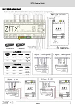
Page 5: ...s dz h 1 1 A Direct expansion system with via radio thermostats and NetBox gateway 1 2 3...

Page 6: ...s D Direct expansion system with wired thermostats and NetBox gateway Z s s Z E t KD z Ed K Ed 1 2 3...

Page 7: ...Pipe FANCOIL Installation Type Individual Collective Location NTC 1 Optional 3 Optional 3 Battery inlet pipe NTC2 Remove resistor Optional 3 Battery inlet pipe 4 Pipe FANCOIL Installation Type Individ...

Page 8: ...peratures protection NTC1 for the pro duction equipment output and NTC2 for the inlet temperatures to the radiant floor To activate in the ZITY the radiant protocol the switches must be positioned as...

Page 9: ...ay The other brands do not require a sensor E K W W Installation type Individual Collective Location NTC 1 Optional 3 Optional 3 Battery inlet pipe NTC2 Remove resistor 4 Optional 3 Battery inlet pipe...

Page 10: ...Static green Damper open Flashing red Zone communication error Tx Random flashing red Flashes every time radio communication arrives 1 7 Control relays The control unit has 7 control relays The funct...

Page 11: ...orresponding manual for each brand t dz 2 1 Configure the control unit switches Consult for other applications The SW1 switch is used to configure the ZITY control unit according to the type of instal...

Page 12: ...ponding radio ID of the ZITY RC unit assign a zone number to each thermostat and select which thermostat will be MASTER or Slave key 2 3 B ZEUS RC thermostats with ZITY RC Assign ID number Zone Master...

Page 13: ...ation on other menus see the advanced settings Go to menu 5 Access settings Access the parameter Master Slave Place in position 1 Flexifan Place in ON position Go to menu 9 Actives Modes Actives Modes...

Page 14: ...iated LED goes out LED R1 Pasarela de comunicaci n m quina LED R2 Modulo de expansi n 7 12 zonas LED R3 Modulo de expansi n 7 12 zonas LED R4 Central combinada W MC LED R5 Central Slave 1 LED R6 Centr...

Page 15: ...close Poor communication The control settings have been changed since the learning process Configure it again Check that the thermostat is in the installa tion Check the location and the batteries in...

Page 16: ...NTC sensor are not connected Or the measured temperature is out of range 4 3 ERROR INDICATOR CAUSE SOLUTION 1 The R6 LED in the relay row is flashing Fancoil mode error The work mode is not sent Impos...

Page 17: ...Fn00 Fan inactive automatic operation Min heat temp Min heat setpoint temperature Selectable from 15 to 21 C Max heat temp Max heat setpoint temperature Selectable from 21 to 30 C Min cool temp Min c...

Page 18: ...munication 1 UNI DIR Unidirectional communication 2 Default values 1 The bidirectional mode entails a high battery consumption service life about 1 year 2 The unidirectional mode consumes less batteri...

Page 19: ...always active OFF Backlight turns off in 15s 05 05 Master Slave 0 Slave 1 Master 06 06 Fan control in Master only On Active OFF Disabled 07 07 Factory Reset On Reset to default values OFF Inactive 08...

Page 20: ...s up in same mode as before the loos of current 16 18 Period programming 2 4 6 periods Default 4 19 Weekly programming Enabling or disabling weekly programming 0 Not active 1 Active 20 Digital input 1...

Page 21: ...n DIP5 ON Slave VRV for Direct expansion installations requires DIP 7 ON Water type 4T installations OFF Master VRV for Direct expansion installations Water 2 T installations by default DIP6 ON Settin...

Page 22: ...ction for T 7 C 3 C Dimensions LxHxZ 85x108x13 mm Weight 0 11 kg ZEUS RC radio thermostat Power 2 1 5 V LR06 AA batteries alkaline Average battery life 1 year or longer The batteries are supplied with...

Page 23: ...any problem you should contact MADEL tech nical support service 902 550 290 who will try to solve any problems and answer any questions about the installation It is important to call from the place wh...

Page 24: ...W K Ky d...

Reviews: