background image

COMPUTER-CONTROLLED  HIGH  SPEED  LOCKSTITCH  BAR  TACKING  MACHINE 

-

-

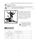
Needle  thread  is  stepped 

on  by  the  work  clamp 
foot at the start of sewing 
(Needle bend)


wiper.(23 to 25mm)

4.

Threads  are

not
trimmed.

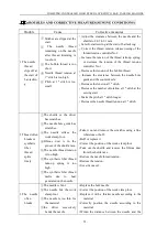
The counter knife is dull.
The  difference  in  level

between  the  needle  hole
guide  and  the  counter
knife is not enough.

The moving knife has been

improperly positioned.

The last stitch is skipped.
Bobbin  thread  tension  is

too low.

Replace the counter knife.
Increase the bend of the counter knife.
Correct the position of the moving knife.
Correct  the  timing  between  the  needle  and  the

shuttle.

In crease the bobbin thread tension.

5.Stitch

skipping
often 
occurs.


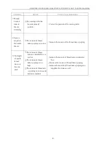
The motions  of the needle

and  shuttle  are  not
properly synchronized.

The clearance between the

needle  and  shuttle  is  too
large.

The needle is bent.
The  driver  excessively

bends the needle.

Correct the positions of the needle and shuttle.
Replace the bent needle.
Correctly position the driver.

6.The needle

thread
comes out
on the
wrong side
of the
material

the needle thread tension is

not high enough.

The tension release

mechanism fails to work
properly.

The needle thread after

thread trimming is too
long.

Number of stitches is too

few.

When sewing length is

short(End of needle
thread protrudes on the
wrong side of sewing
product.)

Number of stitches is too

few.

Increase the needle thread tension.
Check whether or not the tension disc No.2 is

released during bar-tracking.

Increase the tension of the thread tension

controller No.1.

Correct the position of the moving knife.
Use the lower plate, the hole of which is larger

than the presser.

Summary of Contents for ZJ1900DSS-3-04-V4-TP

Page 1: ......

Page 2: ...chine head 8 4 Installing and removing the bobbin case 9 5 Installing the bobbin 9 6 Adjusting the thread tension 10 7 Adjusting the thread take up spring 10 5 MAINTENANCE 11 1 Adjusting the height of the needle bar 11 2 Adjusting the needle to shuttle relation 11 3 Adjusting the lift of the work clamp foot 12 4 The moving knife and counter knife 13 5 Adjusting the wiper 14 6 Draining the waste oi...

Page 3: ...SITION OF THE BUTTON CLAMP 22 5 ADJUSTING THE FEED PLATE 23 6 ADJUSTING THE OPEN ANGLE OF THE BUTTON CLAMP JAW LEVER 23 7 ADJUSTING THE LIFTING AMOUNT OF THE BUTTON CLAMP 24 8 ADJUSTING THE PRESSURE OF THE WORK CLAMP FOOT 24 9 ADJUSTING THE WIPER SPING 25 10 BUTTON SEWING SCOPE 25 III TROUBLES AND CORRECTIVE MEASURES SEWING CONDITIONS 26 IV DRAWING OF THE TABLE 29 ...

Page 4: ...cation 9 lubricating oil 10 supplied by oiler 10 Date recording EPROM 11 Enlarging Reducing facility 20 to 200 1 step in X direction and Y direction respectively 12 Enlarging Reducing Patten enlargement reduction can be done by increasing decreasing the stitch length 13 Max Sewing speed limitation 400 to 3500rpm 100rpm 14 Pattern selection 15 Bobbin thread counter 16 Sewing machine motor 17 Dimens...

Page 5: ...OMPUTER CONTROLLED HIGH SPEED LOCKSTITCH BAR TACKING MACHINE 2 2 CONFIGURATION 1 Names of main unit Work clamp feet Machinehead Thread stand Pedal switch Power switch Operation panel Frame 1 2 5 6 4 7 7 ...

Page 6: ... rod FIX connecting rod to installing hole B of pedal lever with nut When connecting rod is installed in installing hole A the depressing stroke go the pedal is increased 2 Installing the head support rod Drive head support rod in hole in the machine table 1 2 Secure the pedal with a wooden screw in place ...

Page 7: ...achine The flat pad nut followed by a fixed pay attention To prevent possible accidents caused by the full of the sewing machine perform the work by two persons or more when the machine is 3 to the locking nut force if twisted too tightly then the shock result is not satisfactory 1 The oil plate with wood screws fixed in the corresponding position of the platen ...

Page 8: ...r so that it does not come off drain bin when tilting the machine head 5 Tilting the sewing machine head turn head gently down and leaning the head on the head supporting bar at 1 Before tilting the sewing machine head make sure that head support rod is attached to the machine table 2 When raising the sewing machine head do not raise it while holding motor cover It will be the cause of breakage of...

Page 9: ...ccessories box should been installed in the head on the left Be sure to attach this cover to protect the eyes from the disperse of needle breakage Please let the operation panel line connect with the electronic control box according to online identity make sure the connection is correct Connecting the operation panel X7 X8 ...

Page 10: ...n used is low and the oil amount in the hook portion is Refer to 1 DO not lubricate to the places other than the oil tank and the hook of Caution 2 below Trouble of components will be caused 2 When using the sewing machine for the first time or after an extended period of disuse use the machine after lubricating a small amount of oil to the hook portion Refer to2 Adjusting the needle to shuttle re...

Page 11: ...in the needle bar and tighten setscrew If the stitches are made as shown in A attach the needle facing to the direction B to a small extent Turn of the power before starting the work so as to prevent accidents caused by abrupt start of the sewing machine Turn of the power before starting the work so as to prevent accidents caused by abrupt start of the sewing machine 1 When the silicon oil is used...

Page 12: ... tension spring and be pulled out from thread hole Pass the thread through thread hole of the horn section and pull out the thread by 2 5cm from the thread hole Turn of the power before starting the work so as to prevent accidents caused by abrupt start of the sewing machine Turn of the power before starting the work so as to prevent accidents caused by abrupt start of the sewing machine If it is ...

Page 13: ...ad tension The standard stroke of thread take up spring is 8 to 10 mm and the pressure at the start is 0 1 to 0 3N Adjusting the stroke Loosen setscrew and turn thread tension asm Turning it clockwise will increase the moving amount and the thread drawing amount will increase Adjusting the pressure To change the pressure of the thread take up spring insert a thin screwdriver into the slot of threa...

Page 14: ...ar to the position where it is lowered by 0 8 mm to 1 mm from the center of upper marker line engraved on the needle bar After the adjustment make sure that there is no uneven torque When stitch skipping occurs in accordance with the sewing conditions adjust the height of the needle bar so as to lower it by 0 5 to 1 mm from the needle bar engraved line 2 Adjusting the needle to shuttle relation Tu...

Page 15: ... tighten setscrew of Loosen setscrew of the shuttle and adjust the longitudinal position of the shuttle To do this adjustment turn shuttle race adjusting shaft clockwise or counterclockwise to provide a 0 05 to 0 1 mm clearance between needle and the blade point of inner hook After adjusting the longitudinal position of the shuttle further adjust to provide a 7 5 mm clearance between the needle an...

Page 16: ... If the work clamp foot lever support plate interferes with the wiper readjust the height of the wiper using setscrew in the wiper installing base Turn OFF the power before starting the work so as to prevent accidents cause by abrupt start of the sewing machine Loosen adjusting screw so that a clearance of 18 5 mm is provided between the front end of the throat plate and the top end of thread trim...

Page 17: ... stopped after the sewing finished 6 Draining waste oil 7 A mount of oil supplied to the hook When polyethylene oiler becomes filled with oil remove polyethylene oiler and drain the oil 1 Loosen setscrew and remove setscrew 2 When screwing in adjustment screw the amount of oil of oil pipe left can be reduced 3 After the adjustment screw in setscrew and fix it 1 The state of standard delivery is th...

Page 18: ...the RESET key is pressed When the error No E221 is displayed be sure to replenish the designated places below with oil Then start up the memory switch and set No 245 to 0 with the RESET key Outflow the residual oil in gearbox Lubricate the upper gearbox After replenishing the places with oil the error No E220 or No E221 is displayed again unless the memory switch No 245 is changed to 0 Turn OFF th...

Page 19: ... LOCKSTITCH BAR TACKING MACHINE positioning groove Keep the left end of the pulley aligned with the right end of the positioning groove that in the shear driving shaft Then tighten the screw on the pulley reference plane a b c a b c ...

Page 20: ...mming safety sensor chip in the trimming safety sensor then locking the screw to fix the trimming safety sensor When the foot pedal is pressed for the first time presser foot is pressed down and the trimming safety sensor chip does not enter the trimming safety sensor When the foot pedal is pressed for the second time the machine starts to sew and if there is an alarm that the machine is trimming ...

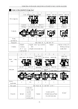
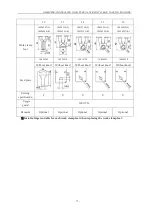
Page 21: ...lied with F type machine head Depends on the destination Optional Standard accessory for M knit goods type machine head 6 7 8 9 10 11 Work clamp foot 10012349 L 10012342 R 10012339 L 10012346 R 10012341 L 10012348 R 10026244 L 10026245 R Feed plate 10012277 10012302 10012286 10012296 10012301 10026246 With knurl With knurl With knurl Without knurl Without knurl Without knurl Sewing specification S...

Page 22: ... R 10026253 L 10026254 R 10026256 L 10026257 R Feed plate 10026249 10026252 10012338 10026255 10026258 Without knurl Without knurl Without knurl Without knurl Without knurl Sewing specification F S S S S guard 10011556 Remarks Optional Optional Optional Optional Optional Install a finger suitable for each work clamp foot when replacing the work clamp foot ...

Page 23: ...crosswise 40 10012303 With knurl processed Sewing area lengthwise 30 X crosswise 40 10014401 t 1 2 Needle hole guide A 1 9 B 2 8 Standard type A 1 6 B 2 6 With relief slit 10004646 Selective spare part A 1 6 B 2 0 Without relief slit Without relief slit 10011757 F and M types A 2 3 B 4 0 Without relief slit 10004727 H and W types A 3 B 7 Without relief slit For net machine 10007281 10047532 ...

Page 24: ...d preparation of the operation 3 Needle and thread Needle Needle thread Bobbin thread DPx17 14 60 80 60 60 50 60 40 60 Be sure to perform the work with two persons or more when moving the sewing machine Installation of the sewing machine head is same as that of the Refer to the instruction manual for the bartacking machine Install a set of the button tray base to a convenient place for the work as...

Page 25: ...just so that the center of the needle enters the center of the button 5 After the adjustment perform the confirmation of the pattern shape and make sure that the needle surely has entered the button hole 1 Place a button in button clamp jaw levers WARNING When change of the shape of button change of the sewing pattern or enlargement reduction of the sewing width is performed make sure the needle e...

Page 26: ...ult in the danger of the needle breakage or the like Also if the pedal is depressed during the adjustment the button clamp unit will go up or come down So be careful Turn OFF the power before starting the work so as to prevent accidents cause by abrupt start of the sewing machine Bring the machine to its stop motion state Then lift button clamp Loosen screw in the button clamp jaw lever and adjust...

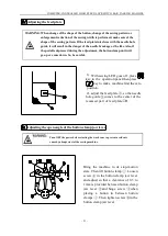
Page 27: ...in the direction of B After the adjustment securely tighten setscrews Adjustment of the pressure of the work clamp unit The pressure of the work clamp unit should be minimized as long as the material does not warp during sewing Loosen adjusting screw and turn adjusting screw to obtain the aforementioned pressure Turn OFF the power before starting the work so as to prevent accidents cause by abrupt...

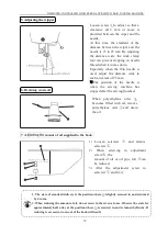
Page 28: ...mming in between wiper and the wiper spring Correct properly the tension after wiper spring so that the tension at that time becomes 20 to 30 g a little higher tension than that of the bobbin thread coming out of the bobbin case If the retaining of the needle thread is excessive the thread may protrude from the upper side of the button Turn OFF the power before starting the work so as to prevent a...

Page 29: ...pitch at 1st stitch longer Decrease the needle thread tension at 1st stitch 2 Thread often breaks or synthetic fiber thread splits finely The shuttle or the driver has scratches The needle hole guide has scratches The needle strikes the work clamp foot Fibrous dust is in the groove of the shuttle race The needle thread tension is too high The synthetic fiber thread take up spring is too high The s...

Page 30: ... The clearance between the needle and shuttle is too large The needle is bent The driver excessively bends the needle Correct the positions of the needle and shuttle Correct the positions of the needle and shuttle Replace the bent needle Correctly position the driver 6 The needle thread comes out on the wrong side of the material the needle thread tension is not high enough The tension release mec...

Page 31: ...d take up spring is too low Increase the tension of the thread take up spring 9 The length of needle thread does not become short The tension of thread tension controller No 1 is too low The tension of thread take up spring is too high The tension of thread take up spring is too low and motion is unstable Increase the tension of thread tension controller No 1 Decrease the tension of thread take up...

Page 32: ...COMPUTER CONTROLLED HIGH SPEED LOCKSTITCH BAR TACKING MACHINE DRAWING OF THE TABLE ...

Reviews: