6
© Copyright 2020 Zoeller
®
Co. All rights reserved.
form the plate plus any amount over 0.008" measured in the field before the
cutter and plate were disassembled from the pump.
H. Installing the cutter plate (29)...
1. Carefully clean the area of pump housing (28) where the cutter plate (29)
will be installed.
2. Install cleaned cutter plate (29) on the pump housing (28) with eight cutter
plate screws (31).
Note: When the cutter plate is installed in the proper direction the eight radial
relief slots will be facing out towards the cutter.
I. Installing the cutter (30)...
1. Install the proper amount of shims (25) on the shaft to obtain the proper
running clearance between the cutter plate (29) and cutter (30).
2. Install the cutter (30) onto the shaft.
3. Install the screw (34), lockwasher (33) and flat washer (32) using thread
locking compound and torquing to 175-195 in/lbs.
Note: Immobilize the cutter by placing a aluminum or brass rod in one of the
holes in the cutter plate.
CAUTION
Do not chip or nick the cutter while using the rod to immobilize
the cutter.
4. With the pump in the vertical position to remove end play, measure the
running clearance between cutter (30) and cutter plate (29) using a feeler
gauge. Repeat 1 thru 3 until .004" to .008" clearance is obtained. (See
cutter clearance diagram on page 3).
Leak Test
(Before oiling pump) Perform a leak test on the pump seals by installing a
regulated air supply into the holes (1/4" NPT access). The motor chamber,
seal chamber and cover chamber must be checked. The pressure of the
air supply should be set at approximately 9 PSI. Submerge the pump in
clear water watching for small air bubbles around square ring seals, rotary
seal, cord connection, and oil fill plugs.
NOTE: Make certain that the pump is placed in the water so that no areas are
present that would trap air (such as the cavity around the lower rotary seal),
not allowing the bubbles to rise to the water surface.
If it is not possible to leak test the pump using the submersion method, a
regulated air supply with a (0-15 PSI) air gage can be installed in the fill
holes. The pump to be pressurized and held at 9 PSI. After removing the
air supply, the pressure should not drop more than 1/2 PSI in a 24 hour
period.
J. Oiling and final assembly.
1. After leak testing has been completed, clean pipe plugs and reapply pipe
dope or teflon tape. Install pipe plug (1) in cover (4).
2. With the pump laying on its side with the oil fill hole up fill the seal chamber
cavity with an anti-wear non-detergent, rust inhibiting, paraffining oil of
approximately 100 SUS. (See table below for acceptable type of oil.)
Refiner
Product Name
Arco
Duro 22 or 32
Exxon
Teresstic 22 or 32 or acceptable equal
Chevron
Clarity Hydraulic Aw ISO22 or ISO32
3. Clean pipe plugs and reapply pipe dope or teflon tape. Install pipeplug
(1) in adapter (19).
4. While pump is on it’s side place approximately one quart of oil in motor
housing. (Use the same oil as used in the seal cavity.)
5. Set the pump upright and finish filling the motor chamber with oil until it
Assembly Procedures (continued)
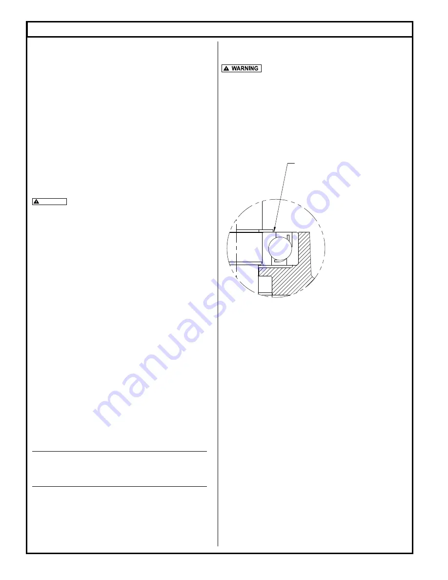
ANGULAR CONTACT BEARING TO BE ORIENTED
SUCH THAT THE FLANGED OR THICKER SIDE
OF THE INSIDE RACE FACES UP AND MATES
AGAINST SNAP RING.
ZEPA0515
LOWER BEARING ORIENTATION
runs back out the fill hole. With the oil running out the fill hole the oil will be
at the proper level for the top bearing.
Do not over fill.
6. Clean pipe plug and reapply pipe dope or teflon tape. Install pipe plug (1)
in motor housing (12).


