background image

CANDTU-200UWGR


CAN Bus Message Recording and Wireless Data Transmission Equipment User Manual 


©2021 Guangzhou ZLG Microelectronics Technology Corp.,Ltd.


37 

User Manual


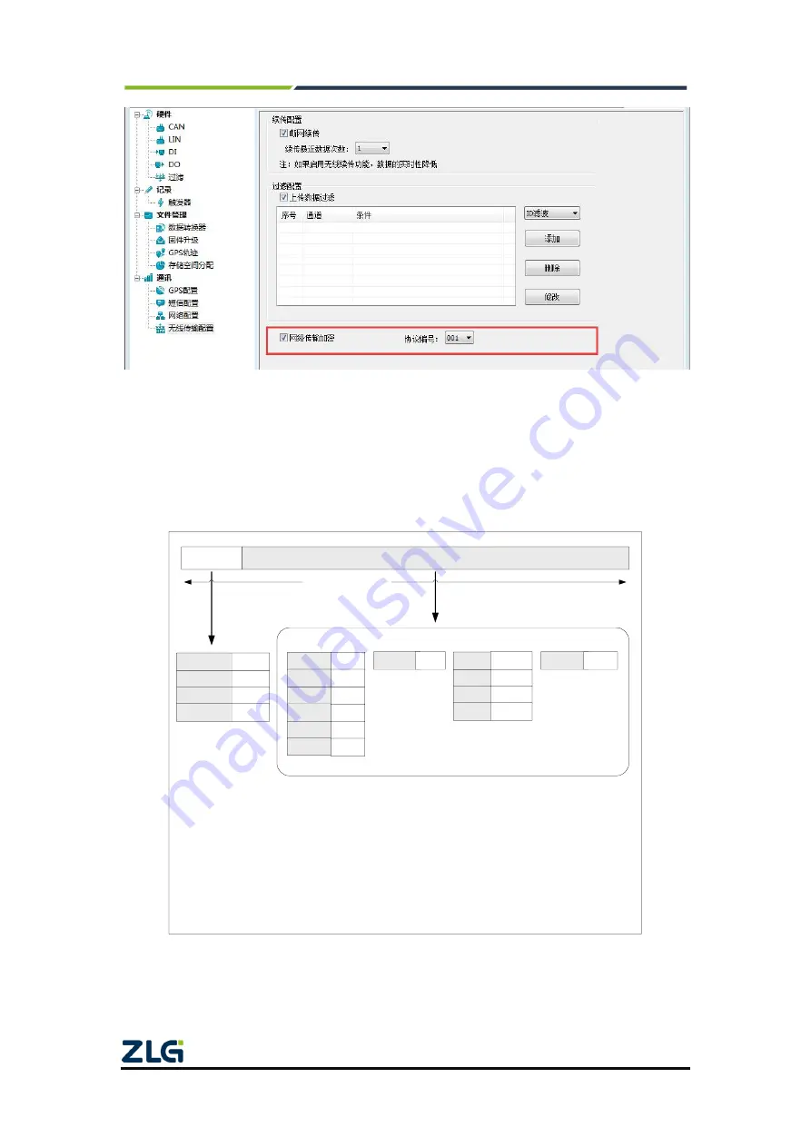
Figure 4.35 Network transmission encryption 

4.2.17  Network Frame Format 

错误

!

未找到引用源。

  shows  the  network  message  communication  protocol  format. 

Special attention: All network packet data are sent and received in big-endian mode. 


数据部分

首部

帧头标志

报文类型

校验和

数据段长度

时间戳

报文

ID

报文信息

通道号

数据长度

报文数据

纬度

经度

速度

时间

CAN报文数据

GPS定位数据

心跳字符

心跳包数据

ID

序列号

设备ID数据

0xAA

1 byte

[1]

1 byte

[2]

1 byte

4 bytes

4 bytes

2 bytes

1 byte

1 byte

8 bytes

0

4 bytes

[3]

4 bytes

4 bytes

12 bytes

8 bytes

[1]:报文类型如下所示


0x01

CAN

报文

0x02

GPS

定位数据

0x03

TICK

心跳包

0x04

:设备

ID


[2]:校验为所有数据的校验,
校验算法:

对所有数据进行按

位异或运算


[3]:GPS定位数据中经度、纬
度、速度均为 float 类型,
时间格式如下:

struct time {
        uint16_t    year;
        uint16_t    mon;
        uint16_t    day;
        uint16_t    hour;
        uint16_t    min;
        uint16_t    sec;
}; 

附注:

网络报文(大端模式)


Figure 4.36 Network frame protocol format 


Summary of Contents for CANDTU-200UWGR

Page 1: ...age Records and Wireless Data Transmission Equipment User Manual UM01010101 V1 03 Date 2019 03 15 Category Contents Keywords CAN Bus message recording and storage Description Product User Guide 2021 Guangzhou ZLG Microelectronics Technology Corp Ltd ...

Page 2: ...n History Version Date Description V0 90 September 18 2017 Created V1 01 October 10 2017 Added the network data frame format V1 02 February 8 2018 Modified the firmware upgrade operation and added the description of the online upgrade function V1 03 March 15 2019 Updated the document header and footer and Sales and Service Network content and added the Disclaimer content ...

Page 3: ...alue Input Interface 10 3 3 4 CAN bus Interface 11 3 3 5 LIN Bus Interface 12 3 4 USB Interface 13 3 5 SD Card Interface 13 3 6 SIM Card Interface 13 4 Configuration Tool Installation and Introduction 15 4 1 Software Installation 15 4 2 Functions 17 4 2 1 Device Selection 18 4 2 2 Device Name Configuration 19 4 2 3 CAN Configuration 19 4 2 4 LIN Configuration 21 4 2 5 DO Configuration 22 4 2 6 Fil...

Page 4: ...4 2 21 Downloading and Obtaining Device Configurations 43 4 2 22 Pausing and Resuming records 43 4 2 23 Clearing Device Storage 43 4 2 24 Device INFORMATION 44 5 USBCAN Function 45 5 1 CANTest Test Software Installation 45 5 2 Quick Use of the USBCAN Function 47 6 Quick Instructions 50 6 1 Operational Guidelines 50 6 1 1 Configuration 50 6 1 2 Records 50 6 1 3 Upgrade 50 6 1 4 Changing the Card 53...

Page 5: ...CAN bus has developed CANDTU series products for troubleshooting CAN buses which can record CAN messages offline and perform GPRS and 4G transmission It can easily complete the message recording and on site monitoring of applications such as vehicles ships elevators wind turbines and construction machinery CANDTU 200UWGR series products are storage type 2 channel CAN bus data recorders The product...

Page 6: ...CANDTU 200UWGR CAN Bus Message Recording and Wireless Data Transmission Equipment User Manual 2021 Guangzhou ZLG Microelectronics Technology Corp Ltd 2 User Manual ...

Page 7: ...torage Storage capacity SD memory card of a maximum of 32 GB Storage mode all storage timing storage Full mode rolling record full stop Trigger mode conditional trigger external trigger Find and location Manual time stamping Data export ASC or CCP data for CANoe CANScope analysis Digital output One digital output Real time clock Built in rechargeable lithium battery Software resources Supports the...

Page 8: ...ion records and fault analysis for traditional vehicles and new energy vehicles Ship CANFD communication fault detection and troubleshooting Coal mine CAN communication fault analysis Elevator operation fault detection and troubleshooting Construction machinery operation fault detection and troubleshooting Operation detection and troubleshooting of aerospace vehicles and ancillary equipment ...

Page 9: ...ting temperature SD card not included 40 85 Storage Temperature SD card not included 40 85 Note The operating temperature of the device depends on the SD card The specifications are as follows SD card specifications 25 C to 85 C operating temperature 40 C to 85 C storage temperature 2 3 Protection Level Table 2 3 Protection level electrostatic discharge immunity test IEC61000 4 2 Interface Conditi...

Page 10: ... 3 1 Class B Capacitive coupling Table 2 5 Protection level surge impact test IEC61000 4 5 Interface Conditions Test level Test voltage kV Test Result Remarks Power supply Level 3 1 Class A Line line Level 3 2 Class A Line ground CAN bus Level 3 1 Class B Line line Level 3 1 Class B Line ground Note For details see the attachment Electromagnetic Compatibility Test Report pdf 2 4 Mechanical Dimensi...

Page 11: ...rfaces of CANDTU series devices 3 1 Interface Layout Figure 3 1 shows the device panel layout Figure 3 1 Panel layout 3 2 Indicators 错误 未找到引用源 describes the indicator status Table 3 1 Indicator status Indicator STATUS State description Power supply Always red The power supply is normal CAN0 1 Green normally on Channel enabled Green flashing Channel data receive and send Flash in red Channel data e...

Page 12: ... 100 ms on 300 ms off Data transmission Closed No SIM card or registration failed 3 3 DB9 Interface Flange Terminal Interface 3 3 1 Power INTERFACE The rated voltage of the power input of the device is 7 5 48 V DC Table 3 2 Table 3 3 and Table 3 4 list the interface schematic diagram signal definition and interface specifications Table 3 2 Power interface Type Schematic Diagram Flange terminal Tab...

Page 13: ...ion DO DO_P Positive pole of the digital output channel DO_N Negative pole of the digital output channel Table 3 7 DO interface specifications parameter Conditions Minimu m Typical value Maximu m Unit Contact load DC 3A resistive 30 V Contact load AC 3A resistive 250 V Contact Resistance DC 1A 24V 0 1 Ω Isolation voltage Valid value 4000 V 设备 输出单元 DO_P DO_N 用户电源 用电设备 Figure 3 2 DO network connecti...

Page 14: ... The device provides one channel digital input The physical form of the interface is a flange terminal Table 3 9 Table 3 10 and Table 3 11 list the interface diagrams signal definitions Table 3 8 DI interface Type Schematic Diagram Flange terminal Table 3 9 Flange terminal signal definition Function interface Signal definition Signal description DI DI_P Positive pole of the digital input channel D...

Page 15: ... including message marking pause recording resume recording and user upgrades 3 3 4 CAN bus Interface The device provides two isolated CAN Bus interfaces The physical form of the interface is a DB9 terminal Table 3 11 Table 3 12 and Table 3 13 list the interface schematic diagram signal definition and interface specification Table 3 11 CAN Interface Type Schematic Diagram Pin description DB9 pin 2...

Page 16: ... network terminal node to eliminate signal reflection on the bus and avoid signal distortion Figure 3 4 shows the high speed CAN network topology The device has a built in 120 ohm terminal resistance which can be configured to turn on or off by using the configuration tool CANDTU For operation details see 4 2 1 Note The bus communication distance and communication rate are related to the field app...

Page 17: ...peed USB2 0 protocol specification and can communicate with PCs compliant with USB1 1 and USB2 0 standards The physical form of the interface is a Type B USB port 3 5 SD Card Interface The device provides one SD card interface which can support SD memory cards of a maximum of 32 GB for storing CAN bus message data The interface adopts a self locking card slot and the SD card can be locked after th...

Page 18: ...r Manual 2021 Guangzhou ZLG Microelectronics Technology Corp Ltd 14 User Manual services of China Unicom China Telecom and China Mobile Put the SIM card into the SIM card tray and push it into the SIM card slot when pulling it out push the yellow dot next to it to take out the SIM tray ...

Page 19: ...ronics Technology Corp Ltd 15 User Manual 4 Configuration Tool Installation and Introduction 4 1 Software Installation 1 Double click the software installation package to install the software The dialog box shown in Figure 4 1 appears Figure 4 1 Installation wizard 2 Click Next The Choose Install Location dialog box appears ...

Page 20: ...nt User Manual 2021 Guangzhou ZLG Microelectronics Technology Corp Ltd 16 User Manual Figure 4 2 Selecting an installation path 3 Click Next The dialog box shown in Figure 4 3 appears Figure 4 3 Selecting the Start Menu folder 4 Click Install The Install Driver dialog box appears ...

Page 21: ... configuration software and driver are installed 4 2 Functions After the program is installed there will be shortcuts to the configuration tool on the desktop and start menu Double click the desktop icon to launch the program The CAN configuration page appears by default as shown in Figure 4 6 The configuration tool interface is divided into four parts 1 Menu bar Provide all operation commands of ...

Page 22: ...n tool to complete the quick operation of commands 3 Side navigation bar Provide multiple categories of information tabs to quickly switch tabs 4 Information settings bar Operate the specific configuration information based on the options in the left navigation bar Figure 4 6 Main page 4 2 1 Device Selection When using the configuration software select the corresponding device model as shown in Fi...

Page 23: ...f the selected model is connected to the computer properly the shortcut toolbar will change from dark to bright as shown in Figure 4 8 Figure 4 8 Device valid 4 2 2 Device Name Configuration To easily distinguish devices when using network transmission CANDTU supports device name customization Users can distinguish CANDTU devices by device name 4 2 3 CAN Configuration Figure 4 9 shows CAN configur...

Page 24: ...el Deselected Disconnect the built in 120 ohm resistor termination resistor of the corresponding CAN channel 5 Custom baud rate If the provided common CAN communication baud rate cannot meet the requirements select the customized baud rate check box click the baud rate calculator to calculate the customized baud rate information The text box displays the current baud rate and sample point informat...

Page 25: ...error frames Selected Record CAN error frames Deselected CAN error frames are not recorded 4 2 4 LIN Configuration The following figure shows the CAN configuration items Figure 4 11LIN Configuration tab 1 Channel selection Selected Enable the corresponding LIN channel Deselected Disable the corresponding LIN channel 2 Communication baud rate Provides commonly used LIN communication baud rates 3 Da...

Page 26: ...2 DO Configuration tab Figure 4 13 GPS area setting 1 Channel enable Selected Enable the corresponding DO channel Deselected Disable the corresponding DO channel 2 Triggering event Record full Trigger output when the SD card is full Bus error Trigger output when the CAN bus is faulty Trigger output when the SD card is abnormal or does not exist In GPS area trigger output when the device is outside...

Page 27: ...ules of each CAN channel are independent of each other and need to be configured separately 1 Channel selection Select an CAN channel for which filtering rules need to be set 2 Acceptance code and mask code Each set of filter items contains an acceptance code and a mask code The acceptance code and mask code are both a 32 bit value Figure 4 15 shows the specific format Figure 4 15 Filter table for...

Page 28: ...ing and all are received There is a one to one correspondence between the acceptance code and the mask code Each CAN channel supports the setting of eight groups of acceptance codes and mask codes 3 Filter calculator For user convenience the configuration tool comes with a filter calculator The required acceptance code and mask code can be generated by specifying the frame ID or specific bits in t...

Page 29: ...s full the device will stop recording Users need to replace the SD card before recording 4 2 7 2 Record mode The device supports five recording modes 1 Long time record As shown in Figure 4 18 select Long Time Recording After the device is powered on it will record related information based on the configuration Figure 4 18 Long record 2 Condition record As shown in Figure 4 19 select the condition...

Page 30: ...cording is selected When no trigger condition occurs the device records the number of frames according to the configured pre trigger and buffers the corresponding number of latest packets until the trigger condition occurs Save the pre cached data and continuously record the packets received in the subsequent period based on the configured time Figure 4 20 Pre trigger record 4 Timing record As sho...

Page 31: ...ased on the configuration and only saves the last message received by the ID within the cycle time If the specified ID message is not received within the period there are three processing methods Not recorded Record with last received data Record with custom data Figure 4 21 Timing record 5 Not recorded As shown in Figure 4 22 if the no recording mode is selected no data will be recorded during no...

Page 32: ... latest functions contact our sales or technical support personnel As shown in Figure 4 23 and Figure 4 24 select the original data for data conversion Figure 4 23 Data converter general settings 1 Select the original data path and click the Refresh button The information list will list all data files 2 By dragging the time bar select the data of the time range to be converted 3 Select the output ...

Page 33: ...e following rules Folder Name Index Default The file name is determined based on the selected target directory If the directory is Data the file names are Data1 Data2 Index pure index named filename such as 1 2 Date and time Name the file based on the timestamp of the first frame in the file such as 2015 10 10_09 34 23 6 Operation button Start conversion Stop conversion The converted data is retai...

Page 34: ...4 bus off E5 bus overload DATA1 bit7 send buffer error bit6 receive buffer error bit5 overload error bit4 padding error bit3 format error bit2 CRC error bit1 response error bit0 bit error 4 2 9 GPS Track As shown in Figure 4 25 draw items for the GPS track Click Browse As shown in Figure 4 26 select the folder where the track file GPX recorded by the device is located Click OK On the multi file me...

Page 35: ...UWGR CAN Bus Message Recording and Wireless Data Transmission Equipment User Manual 2021 Guangzhou ZLG Microelectronics Technology Corp Ltd 31 User Manual Figure 4 25 GPS track Figure 4 26 Selecting a track file ...

Page 36: ...l 2021 Guangzhou ZLG Microelectronics Technology Corp Ltd 32 User Manual Figure 4 27 Merging trajectory files Figure 4 28 Drawing a track 4 2 10 Storage Space Allocation Figure 4 29 shows the storage space allocation item Users can freely allocate memory space for each valid recording channel ...

Page 37: ...tion 4 2 11 GPS configuration Figure 4 30 shows the GPS configuration item Figure 4 30 GPS configuration 1 Channel enable If selected enable GPS channel track recording If not selected disable GPS channel track recording 2 System selection Automatically selected The device automatically selects an available GPS positioning system Beidou Only use the Beidou system to provide positioning data ...

Page 38: ...Figure 4 31 SMS configuration 1 Number settings Set the target number for SMS notification 2 Function enable If selected enable the SMS alarm function If not selected the SMS alarm function is disabled 3 Function selection The record is full An alarm is generated when the channel space is full Bus error CAN bus error An alarm is generated If the storage status is abnormal or the SD card is abnorma...

Page 39: ...ion is disabled and the data is sent and received remotely 2 Protocol type TCP client Set the device as a TCP client currently only this configuration is supported 3 Local port Set the local TCP client port number 4 Remote address Set the remote server address to an IP address or domain name 5 Remote port Set the communication port number of the remote server 4 2 14 Network Transmission Filtering ...

Page 40: ...mission after disconnection which minimizes the risks of data loss caused by network quality Figure 4 34 Continuous transmission after network disconnection 4 2 16 Network Transmission Encryption To Be Customized The CANDTU supports network transmission encryption and includes the encryption algorithm library provided by the customer in the device firmware in advance After encryption by using the ...

Page 41: ...are sent and received in big endian mode 数据部分 首部 帧头标志 报文类型 校验和 数据段长度 时间戳 报文ID 报文信息 通道号 数据长度 报文数据 纬度 经度 速度 时间 CAN报文数据 GPS定位数据 心跳字符 心跳包数据 ID序列号 设备ID数据 0xAA 1 byte 1 1 byte 2 1 byte 4 bytes 4 bytes 2 bytes 1 byte 1 byte 8 bytes 0 4 bytes 3 4 bytes 4 bytes 12 bytes 8 bytes 1 报文类型如下所示 0x01 CAN报文 0x02 GPS定位数据 0x03 TICK心跳包 0x04 设备ID号 2 校验为所有数据的校验 校验算法 对所有数据进行按 位异或运算 3 GPS定位数据中经度 纬 度 速度均为 float 类型 时间格式如下 ...

Page 42: ...ANDTU item as shown in 错误 未找到引用源 Figure 4 37 Device selection 2 Configure the server as shown in 错误 未找到引用源 Set Device Index Number and Channel Number Select Server as the work mode Set the local port to be the same as Remote Port under Network Configuration of the CANDTU configuration software Click OK and start CAN to start the web server Figure 4 38 Configuration interface 3 Wait until the devic...

Page 43: ...logy Corp Ltd 39 User Manual Device Operation to view the information of the currently connected device as shown in Figure 4 39 Figure 4 39 Device information selection Figure 4 40 shows no device connected Figure 4 40 Device Information 4 Figure 4 41 shows the device connection The data display area displays the data sent and received ...

Page 44: ...Manual 2021 Guangzhou ZLG Microelectronics Technology Corp Ltd 40 User Manual Figure 4 41 Data sending and receiving 5 As shown in Figure 4 42 click Parameter Device under Device Operation to view the GPS uploaded location information as shown in Figure 4 43 Figure 4 42 Parameter setting ...

Page 45: ...ration file Save default configuration Manually save the current configuration in the program installation directory It is automatically loaded when the program starts and automatically saved when the program stops Save project configuration Save the current configuration in another copy so that it can be loaded and used again later Export configuration Save another copy of the current configurati...

Page 46: ...tcut Bar Figure 4 45 Device menu 4 2 20 Setting and Getting the Device Clock Click Set Real Time Clock in the device menu or the corresponding button in the toolbar The dialog box shown in Figure 4 46 appears 1 Click Set Time The program will set it to the device based on the time combination set in the date and time selection box selected by the calendar on the left 2 Click Set device time to cur...

Page 47: ...nformation on each device page to the device After the configuration is downloaded successfully the device will be in the configuration stage for a short time No other device operations can be performed at this time 2 Obtain device configurations After clicking Get Device Configuration or the corresponding button in the toolbar from the device menu the program will obtain the current configuration...

Page 48: ...s indicating that data is being cleared When the data is cleared the dialog will close automatically This function helps users directly clear the previously recorded data when the device is connected to the computer 4 2 24 Device INFORMATION Device information is used to display the firmware version hardware version serial number current recording status of the device SD card status and other devi...

Page 49: ... two CAN interfaces The PC can be connected to the CAN Bus network by using the USB bus of the device to realize the mutual data transmission between the PC and the CAN Bus network 5 1 CANTest Test Software Installation Find the CANTest software in the CD ROM use this version or later Double click the CANTest_Setup_V2 63 exe software to install it The dialog box shown in Figure 5 1 appears Figure ...

Page 50: ...ngzhou ZLG Microelectronics Technology Corp Ltd 46 User Manual Figure 5 2 Selecting an installation path Click Install The license agreement dialog box appears as shown in Figure 5 3 Figure 5 3 License Agreement dialog box Click Yes to complete the software installation Figure 5 4 Installation complete ...

Page 51: ...USB cable connect the two CANs of the CANDTU 200UWGR to each other and connect the power cable to the CANDTU 200UWGR Run the CANtest software installed in the previous section on the PC as shown in Figure 5 5 Figure 5 5 CANTest software After starting CANtest select a device type We choose CANDTU The parameter setting interface of the device is displayed as shown in Figure 5 6 The baud rates of CA...

Page 52: ...start CAN button or click OK Click Start on the data operation interface as shown in Figure 5 7 If the device is connected properly no message appears if the connection is abnormal an error message appears Figure 5 7 Start CANDTU 200UWGR On the tab page of any CANtest software click the Send button You can then receive the data you just sent on the tab page of another CANtest software as shown in ...

Page 53: ...GR CAN Bus Message Recording and Wireless Data Transmission Equipment User Manual 2021 Guangzhou ZLG Microelectronics Technology Corp Ltd 49 User Manual Figure 5 8 Communication between dual CANs of the CANDTU 20UR ...

Page 54: ...ry of the CANDTU configuration software directory 3 Perform download Click the download configuration button in the CANDTU configuration software After the download is complete the device directly enters the recording state Note When you use the device for the first time synchronize the device clock once by using the CANDTU configuration software 6 1 2 Records 1 Enter the record If no fault occurs...

Page 55: ...in the recording state the upgrade is successful and the device automatically restarts and enters the working state If you hear continuous beeps the upgrade fails 2 Online upgrade 1 Run the configuration tool and select the corresponding device model as shown in Figure 6 2 If the device is connected successfully the Device Information option in the configuration tool changes from gray to blue and ...

Page 56: ...ing upgrade After the upgrade is successful the Firmware verification is successful waiting for the device to restart automatically to complete the update message is displayed After the device restarts the Device Information option in the configuration tool returns to the blue state and the device information can be viewed Check whether the device has been successfully upgraded to the specified ve...

Page 57: ...e Card 1 Pause recording Pause recording by using the configuration software or disconnect the power failure detection signal first The device enters a suspended state the SD card saves data and the device stops 2 Pull out the SD card and remove the SD card in the pause state The device does not sound an alarm 3 Insert the SD card and reinsert the SD card The device automatically resumes recording...

Page 58: ...__________________________________________________________ _______________________________________________________________________ _______________________________________________________________________ _______________________________________________________________________ _______________________________________________________________________ _____________________________________________________...

Page 59: ...er Manual Product return procedure 1 Provide proof of purchase 2 Obtain a return authorization from a dealer or branch 3 Fill in the product fault report form and state the reasons for the repair and the symptom in detail so as to minimize the repair time Carefully package the product and send it to maintenance department with a fault report form attached ...

Page 60: ...td ZLG Electronics will try to present detailed and accurate product information in this manual However due to the effectiveness of this manual within a particular period of time ZLG Electronics does not guarantee the applicability of this document at any time ZLG Electronics shall reserve the right to update this manual without prior notice To get the latest version please visit the official webs...

Page 61: ...uipment User Manual 2021 Guangzhou ZLG Microelectronics Technology Corp Ltd 57 User Manual Dreams come true with professionalism and dedication Guangzhou ZLG Electronics Co Ltd For more details please visit www zlg cn Welcome to call the national service hotline 400 888 4005 ...

Reviews: