


1
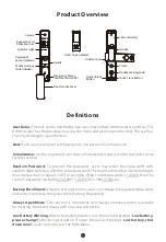
Product Overview
Definitions
Note
:
Each user can register ten fingerprints, one password, and one card.
Initialization:
All the registered user data will be deleted and it will be restored to the
factory settings.
User Roles:
The lock can be handled by two user roles namely Administrator and User. The
Administrator has the privilege to access the menu and also to open the door. The user has
the only privilege to open the door.
Random Password:
To protect the password, users may enter their password with
random digits before or after the actual password. The maximum number of entered digits
must be less than or equal to 30. For example: If the correct password is 123456, then the
random password can be 89123456807, 1234562363, 389123456, etc.
Backup Enrollment:
After the first registration, users can change the registered password
and card, or continue to register the remaining fingerprints.
Always Open Mode:
This function is to keep the door always unlocked, which is suitable
for meeting rooms and places with no access restriction.
Low Battery Warning:
When the battery power is low, the lock will prompt “
Low battery,
please change!
” after being turned on. If lower, the lock will prompt ”
Low battery, shut
down soon!
”, users cannot access the Main Menu.
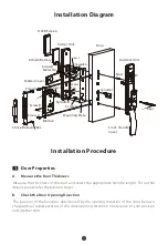
Lithium Battery
Hidden Cover
Front Handle Cover
Handle
Clutch
Double Locking Knob
Quick Close Button
Camera
Keypad & Card
Detection Area
Indicator Light
Fingerprint
Sensor (Hidden)
Quick Unlock
Button
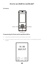
OLED Screen Model
Handle
Mechanical Key
Hole (Hidden)
Emergency Power
Interface (Micro USB)


