background image

Barrier Gate-ProBG3000 Series


User Manual 

P a g e

 | 7


Copyright©2020 ZKTECO. CO., LTD. All rights reserved.


3.2


Adjust Spring Setting 

According to the length of the boom, assemble the compression spring. Also, tighten or loosen the 
adjusted handle to maintain the boom stable at 45°. It is the best way to test spring strength. 

Exceptions: 

When there is a power failure, the barrier gates  open automatically, and a greater spring force is 
required. 

3.3


Testing Spring Setting 

1.


Open the door of the barrier machine case with a key and remove the mounting plate. 

2.


Unplug the power cord. 

3.


Manually adjust the boom to the position of about 45° and release hand. 

4.


If the boom is stable in this position and does not move, it indicates that the spring adjustment 

is correct. 


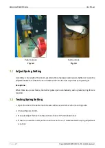
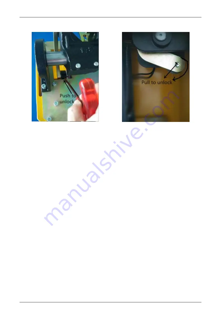
Push to unlock


Fig. 3.2 


Pull to unlock 

Fig. 3.3 

Summary of Contents for ProBG3000 Series

Page 1: ...eries Date November 2020 Doc Version 1 3 English Thank you for choosing our product Please read the instructions carefully before operation Follow these instructions to ensure that the product is func...

Page 2: ...8 4 2 TECHNICAL PARAMETERS 10 5 CONTROL BOARD PIN DIAGRAM 12 5 1 DIP SWITCH SETTINGS 13 5 2 INPUT INTERFACE 14 5 3 OUTPUT INTERFACE INTRODUCTION 14 5 4 CONNECTING TO OTHER PARKING DEVICE 15 5 4 1 Lic...

Page 3: ...ble control panel humanized interactive appearance design and anti collision protection gate connector design 1 2 Appearance Fig 1 1 2 2 1 Installation Precautions Before installing the parking barrie...

Page 4: ...he installation position of the cabinet Drive four expansion bolts into the bolt holes as shown in Fig 2 2 Install screw pads and use a spanner to tighten nuts as shown in Fig 2 3 Fig 2 2 Fig 2 3 Chas...

Page 5: ...the factory accordingly The spring used in the mechanism is in a highly tense state And all the adjustments of the barrier must be carried only after the spring is in a loose state Please check the s...

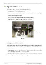
Page 6: ...g 3 1 Use the torque wrench to tighten the two fastening screws 72 Nm Fig 3 1 Unlocking Arm Manually When Power is Off When there is no power the barrier gate maybe in a vertical or horizontal mechani...

Page 7: ...spring strength Exceptions When there is a power failure the barrier gates open automatically and a greater spring force is required 3 3 Testing Spring Setting 1 Open the door of the barrier machine...

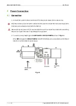
Page 8: ...to connect the main power supply the internal power is already connected to the factory After switching the power off it is recommended to wait for at least 10 seconds before switching the power on ag...

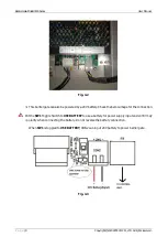
Page 9: ...also be powered by a 24V battery Check the below image for the connection Put the SW1 Toggle Switch to USE BATTERY to use a battery for power supply input and confirm polarity when connecting the batt...

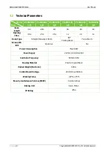
Page 10: ...3m 3m 4m Opening Time 0 9s 2 5s 4 5s 1s 2s 3s Boom Type Straight Telescopic Boom 90 Folding Boom Fence Boom Boom with LED Optional No Power Consumption Max 100W Power Supply 24V DC AC 100 to240V Contr...

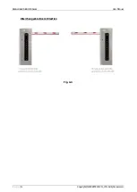
Page 11: ...Barrier Gate ProBG3000 Series User Manual P a g e 11 Copyright 2020 ZKTECO CO LTD All rights reserved Interchangeable Boom Direction Fig 4 4...

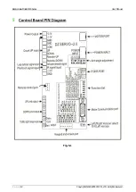
Page 12: ...Barrier Gate ProBG3000 Series User Manual P a g e 12 Copyright 2020 ZKTECO CO LTD All rights reserved 5 Fig 5 1...

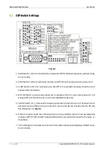
Page 13: ...itch 4 auto closing speed can be adjusted ON is for auto closing speed of 1 3s whereas OFF is for 0 9s for the boom for the ProBG3030 model only 5 The DIP Switch 5 6 7 8 are used for delaying automati...

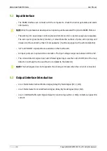
Page 14: ...sses by must be equipped with a vehicle detector UP and DOWN signal ports are available on the mainboard All input ports are in optoelectronic isolation The input voltage range lies between DC5 to 24V...

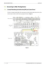
Page 15: ...ts reserved 5 4 Connecting to Other Parking Device 5 4 1 License Plates Recognition Machine LPR and Control Panel The boom lifts automatically after LPR recognizes and verifies license plates the func...

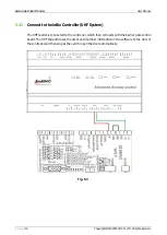
Page 16: ...nnect to the inBio Controller UHF System The UHF reader is connected to the controller which then connects with the barrier gate control board The UHF tag authorizes the user s card number information...

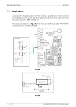
Page 17: ...rking system consist of the loop loop detector and control board The loop is installed under the ground When the loop detects a vehicle the boom resists falling After the vehicle pass the boom falls a...

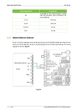
Page 18: ...the inductance value is between 100 uH and 200 uH 3 6 m 5 6 turns 6 10m 4 5 turns 10 25 m 3 turns 25 m 2 turns 5 4 4 Infrared Intrusion Detector If a car or person exists between the transmitter and...

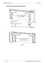
Page 19: ...Barrier Gate ProBG3000 Series User Manual P a g e 19 Copyright 2020 ZKTECO CO LTD All rights reserved Installation of the Infrared Photocell Beam Detector Fig 5 8...

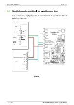
Page 20: ...g e 20 Copyright 2020 ZKTECO CO LTD All rights reserved 5 4 5 When the loop detector and the IR are used at the same time Check the wiring diagram Fig 5 9 to view the connections when the loop detecto...

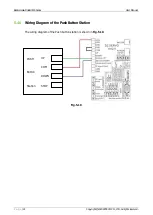
Page 21: ...ser Manual P a g e 21 Copyright 2020 ZKTECO CO LTD All rights reserved 5 4 6 Wiring Diagram of the Push Button Station The wiring diagram of the Push button station is shown in Fig 5 10 Fig 5 10 PUSH...

Page 22: ...al starts flashing which indicates the match is successful 2 Delete Press the White Button for about 10s until the red light starts blinking which indicates that deletion occurred successfully NOTE Th...

Page 23: ...er Value 4 PA__AST Reset NOTE After resetting the parameter value the control board will give an alarm At this time select the parameter PA_31 and press the Enter key to change 1d0000 to 1d0001 _Err E...

Page 24: ...r the mechanical movement is proper Check the connection of the motor or change mainboard Check if the boom is in the balance position 5 44_Err Issue Improper motor encoder plug connection or mainboar...

Page 25: ...for each press 0 to 9 ENTER ENTER key is used for entering into the specific parameter setting item Parameter Interpretation 1d0000 2d0000 3d0000 and4d0000 indicates that the current parameter is 000...

Page 26: ...esent the ratio of acceleration and deceleration For example A value of 30 is 1 1 greater than 30 is acceleration and less than 30 is deceleration Close Position Parameter PA__20 01 to 9999 Open Posit...

Page 27: ...7850 PA__10 1850 PA__10 1100 PA__10 550 PA__11 1800 PA__11 4200 PA__11 5350 PA__12 55 PA__12 50 PA__12 20 PA__13 1650 PA__13 750 PA__13 400 PA__14 1900 PA__14 4750 PA__14 6150 PA__15 85 PA__15 55 PA__...

Page 28: ...NOTE Set the boom length before adjusting the parameters Replacing the long boom with a shorter boom requires the spring to be removed for balance Once parameter settings are reset the machine will a...

Page 29: ...e 29 Copyright 2020 ZKTECO CO LTD All rights reserved 6 4 Packing Accessories List Part Name Quantity M14 150 Chassis Fixing Screw 4 pcs Chassis Fixing Press Plate 2 pcs Remote Controller 2 pcs Chassi...

Page 30: ...t Ltd Address B 1 Khata No 31 Devasandra Industrial Estate Whitefield Main Road Beside Phoenix Mall Mahadevapura Bengaluru 560048 Karnataka India Phone 08068281342 www zkteco in Copyright 2020 ZKTECO...

Reviews: