P/N 501-1787ZE-1-09 • REV 09 • ISS 16APR14
3 / 4
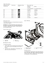
Table 2: Tone settings
SW2-6 device mode
switch setting
Device mode
SW2 switch setting
-1 -2 -3
Mapping input type
Fast flash
Steady
Tone type
Tone A primary/alert
Tone B secondary/evac
OFF
ZP755
0
Intermittent
Continuous
OFF
ZP755
1
Continuous
Intermittent
OFF
ZP755
2
Continuous
Two-tone
OFF
ZP755
3
Two-tone
Continuous
OFF
ZP755
4
Two-tone
Intermittent
OFF
ZP755
5
Intermittent
Two-tone
OFF
ZP755
6
Not used
ON
ZP754
7
Intermittent
Continuous
Setting the volume
The sounder has a volume control potentiometer to adjust the
volume. Refer to Figure 5.
WARNING:
To conform to EN 54 Part 3 sound output levels,
the volume control
must
be set to the full clockwise position. If
the volume is adjusted for any reason, it
must
be returned to
the full clockwise position.
Figure 5: Volume control
1
2
3
1
2
3
4
1.
Tone Select
2.
SW2-6 on
3.
SW2-6 off
4.
Volume control
Mounting the sounder
To mount the sounder:
1. Insert four M4 X 25 mm screws through the PCB mounting
holes, and then secure to the backbox surface. Refer to
Figure 6.
2. Install the sound output assembly into the backbox, and
then secure using mounting screws.
Figure 6: Mounting
3064-01
1
2
3
4
1.
M4 × 25 mm screws
2.
Mounting screws
3.
Sound output assembly
4.
PCB
Sounders per loop
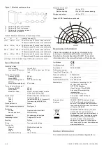
The ZP755WV-2R sounder can be powered directly from the
loop of a ZP3 panel. Use Table 3, in conjunction with Figure 7,
to determine the quantity of detectors and sounders that can
be connected to a two-core shielded loop.


