Z.I.P.P.E.R MASCHINEN GmbH
www.Zipper-maschinen.at
Gartenpflegeset / Garden maintenance set ZI-GPS70G / ZI-GPS182G
Seite 47
13
OPERATION
For operation all safety devices and the belt must be used!
13.1
Assembly
N O T I C E
Take care at the assembly that at existing dovetailings these intrude on each
other.
13.1.1
Power unit
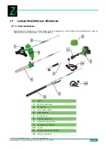
• Mount the rod to the control panel 11 according to FIG B on the drive unit 1 and
attach it with the Allen screws.
• Then push the handle 28 on the extension rod 2 (Fig. C) and secure it with the Allen
screws.
13.1.2
Brushcutter or trimmer
• Then on the brushcutter attachment, the protective cover to be mounted according
to Figure 8 D, and secure it with the Allen screws.
• Then the sheet has or trimmer receiving 29 mounted on the bar (Fig. D).
This process is described in detail in chapter work.
13.1.3
Twig saw
•
Befestigen Sie anschließend die Astsägeeinheit
4
laut Fig. E auf die zugehörige
Stange und ziehen Sie die Inbusschrauben an
13.1.4
Hedge Trimmer
• Then attach the hedge trimmer 3 according to Figure G on the associated extension
rod and tighten the Allen screws.
13.1.5
Mounting the desired implement (Fig. F)
• Prior to this work, the motor must be stationary!
• First screw the thumb screw 12.
• Then press the safety cover 13 to the outside.
• Press the lever below 13 and remove the rod mounted to the tool.
• Add the new rod into the opening.
• Press the lever again and make sure that engages when you release the lever 13a of
the hook inside the hole.
• Press the cover 13 to the rod and turn the hand screw 12 again.
• Hook the end even the strap 10 in the associated hole (see Figure A).

