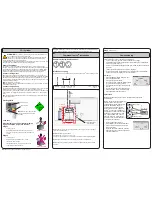
804053UK CS Res Quick Start Guide June 2016 - V3.01
Command-Centre
TM
installation
CO
2
Cylinder
Example HydroTap
®
G4 Classic model
Arc / Cube
Elite
Classic
Step 4-
Installing the Command-Centre
TM
. Also refer to 803341UK Tap installation instructions
(for Arc / Cube also refer to the tube kit assembly instructions) supplied with the tap.
GAS IN
WHITE
POWER
CABLE
USB
MAINS IN
SPARKLING
OUTLET
CO2
IN
BLUE
CHILLED
OUTLET
BRAIDED
Cold isolation valve
(not supplied)
Clearance
Envelope
535mm
Note
All plastic / silicon tubes must be trimmed to size. They must have a constant
fall to the Command-Centre
TM
.
Note
Mains hose length is 750mm.
Electrical power cable length is 3.0m nom.
Position the Command-Centre
TM
according to the hose and cable lengths supplied.
280mm
50mm
50mm
Braided hose fitting
Install the mains water braided hoses to the Command-Centre
TM
before locating in place.
Note
Neither the braided hoses or the tubes supplied can be lengthened.
Note
Chilled and sparkling outlet tubes must be insulated with the foam insulation
provided.
Commissioning
OPEN Position
CLOSED Position
ON
OFF
Stop cock
operation
Have a bucket or similar container (not
supplied) at the ready to hold a
quantity of water that will be ejected
while the filter flush mode is in
operation. Open the filter access
door on the front of the Command-
Centre
TM
and the filter cartridge will
be exposed. Located to the rear right
hand side of the cartridge is a flush
line, approx 600mm long, and the
flush line stop cock. Place the free
end of the flush line into the bucket
or container (not supplied).
Note
At first commissioning, the system will select filter flush screen
automatically.
•
Press the [MENU] button for main menu.
•
Press the [Install] button.
•
Press the [Purge CO] button.
•
In the next screen, press the [START] button
to commence the purging process.
•
You will hear the CO
2
gas running through
the tap.
•
Run for 10 seconds to fully purge the CO
2.
•
Press the STOP button to stop the purge.
•
Press [NEXT] for filter flush screen.
CO
2
Purge
Step 5-
Commissioning.
•
Open the flush line stop cock.
•
Press [START] button to start filter flush.
•
Allow at least 10 litres of water to flush
through the filter.
•
Once the filter flush is finished, close the
flush line stop cock, then press [STOP] to
end filter flush mode.
Filter flush
The HydroTap
®
G4 is now ready to be commissioned.
•
Turn on the power, gas and water and check for any leaks.
•
Familiarise yourself with the operation of the HydroTap
®
G4 in preparation
for use (see User manual).
•
Follow the installation instructions below (and review section C of the User
manual).
•
Initially you will be prompted to select the language.
•
After commissioning, the system may be customised by selecting further
options in section G - Settings, of the User manual.
WARNING!
The cylinder ( containing 1kg of CO
2
) should be installed in a
well ventilated area of area no less than 38m
3
.
If more than 1 gas cylinder containing 1kg of CO
2
is present within the same
location, the recommended ventilation area should be in proportion to the
number of gas cylinders stored in that location.
A ventilated area in a non-enclosed area which could include the kitchen, living room etc.
See gas cylinder and MSDS sheet for complete list of warnings.
Secure the cylinder
Secure the gas cylinder supplied to a suitable wall, within 1 metre of the Command-
Centre
TM
, in an upright position. This is undertaken by screwing the metal bar holding the
Velcro strap to a cupboard wall, 200mm above the floor or base of the cupboard. Make
sure the gas cylinder can stand in place before securing to the wall. Due to regulatory
requirements the gas cylinder must be stored securely and in an upright position.
Connect the regulator
Remove the gas cylinder from the strap. Make sure the regulator knob is turned fully
anti-clockwise to the end-stop before fitting. Screw on the regulator (clockwise). Be aware
that some CO
2
may be discharged from the connection to the regulator as the cylinder
and the regulator are be assembled together. Any CO
2
released will be cold. Screw on the
regulator to stop this leakage.
Note
the leaking CO
2
will be cold.
Note
Two plastic seals are supplied with a new regulator. Only one is required, the other
is supplied as a spare part.
Connect the gas hose
Connect the threaded end of the braided gas hose to the regulator, then connect the push
fit fitting to the top of the Command-Centre
TM
via connection marked ‘CO
2
IN’ .
To turn the gas on, rotate the black knob on top of the cylinder clockwise. Then adjust the
outlet pressure, by rotating the regulator knob clockwise to between 2.7- 3.0 bar (green
zone).
Note
The arrow should sit in the green zone of the regulator gauge; it should not fall in
the red or yellow zones.
CO
2
Regulator
ON - OFF knob
Note
When removing hose, take
care not to lose plastic olive from
the fitting.
Green indicator
Leak test
Faulty seal joint
Good seal joint
After replacing a cylinder or after making
a gas connection, perform a leak test
Stage 1
•
Turn the gas off.
•
Using soapy water applied with a sponge, or with a
brush, cover all of the gas joints with a liberal amount
of suds.
Stage 2
•
Turn the gas on.
•
Adjust the pressure to between 2.7- 3.0 bar.
•
Inspect the joints for leaks.
•
If any bubbles appear to grow, the joint will need
to be resealed and tested again.


