


COMMAND STATION MX1, MX1HS, MX1EC Page 9
11. The Configuration Variables
acteristics by means of configura-
ion variables. New features are introduced at the ZIMO web site
www.zimo.at
The command stations offer the possibilities to modify certain char
t
or can be studied in
new editions of this manual.
e “MAN” key and enter “100” as the command station address.
How to program or read out configuration variables is covered in the chapters “Addressing and Pro-
gramming” of the cab manuals (MX31…). The usual programming procedure is started by pressing
the “E” key followed by th
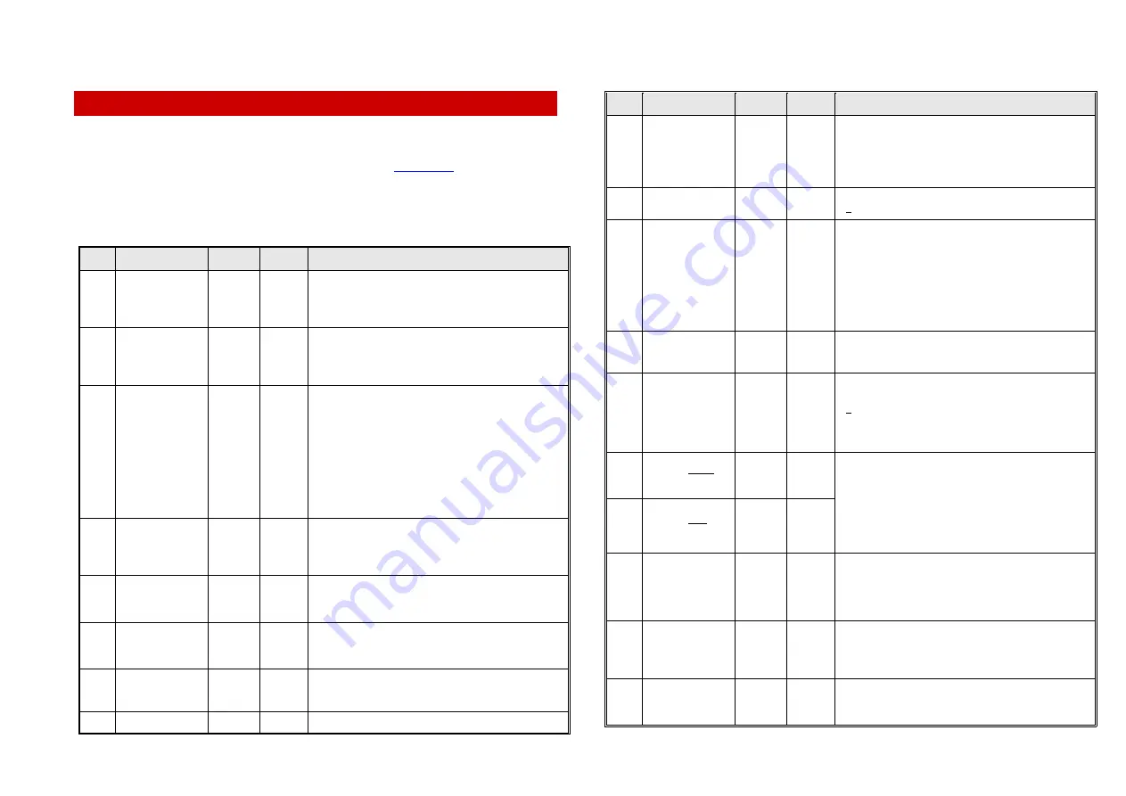
CV
Name
Range
Default Description
#5
Max. c
SCHIENE 1 (MAIN)
0 - 80
0 - 8 A )
This CV defines the maximum allowable current for output
(MAIN track) before the over-current protection
t shuts the power off.
urrent on
( =
80
( = 8 A )
“SCHIENE 1”
is triggered tha
(Default 80 = 8 A)
#6
SCHIENE 2 = PROG
0 - 8 A
( = 8 A )
k) before the over-
triggered that shuts the power off.
Max. current on
0 - 80
( =
80
This CV defines the maximum allowable current for output
NE 2” (MAIN trac
“PROG” or “SCHIE
current protection is
(Default 30 = 3 A for MX1, 80 = 8 A for MX1HS)
#7
Switch-off delay
SCHIENE 1 (MAIN)
0 - 254
( =
2 - 508
250
( =
0,5 s )
cuit)
r the
oltage is
-
er the delay time if necessary.
ms )
After an over current situation is recognized (i.e. short cir
nt” fo
the command station switches to a “holding curre
duration of the delay time, which means the track v
being reduced to limit current flow to 10A. After the delay
time has elapsed, the output is shut-off completely (i.e.
“UES”). With this procedure it is possible to bridge very brief
short circuits that often occur at frogs without shutting the
layout down.
The default delay is for some application too long (a “short”
could leave burn marks on N-scale wheels) and it is recom
mended to low
#8
Switch-off delay
SCHIENE 2
0 - 254
( =
2 - 508
250
( =
0,5 s )
e
for MX1HS; the delay time of the MX1 is always limited to
ms )
Same as CV # 7, but for “SCHIENE 2” or “PROG” output.
NOTE: The full range of adjustment in CV #8 is only effectiv
100ms (can only be varied between 0 and 100ms).
#9
SCHIENE 1
Volt meter
corrections
90 - 110
102
Larger CV value = smaller display value
and vice a versa.
(Adjusting range about 2 V).
#10
Volt meter
corrections
SCHIENE 2
90 - 110
102
Larger CV value = smaller display value
and vice a versa.
(Adjusting range about 2 V).
#11
ing
1-Bit“
microsec
ied in length de-
rds. Useful for some third party
DCC Tim
= Length of „
146 - 162
158
The short DCC bits (value “1”) can be modif
viating from the NMRA standa
decoders.
#12
RS 232
1 - 6
4
= 1: 1200 bit/s
CV
Name
Range
Default Description
Bit rate
( =
1200 bit/s
( =
bit
)
it/s
t/s
to
38400
bit/s )
9600
/s
= 2: 2400 b
= 3: 4800 bi
= 4: 9600 bit/s
= 5: 19200 bit/s
= 6: 38400 bit/s
#13
Handshake
ke
RS 232
0, 1
1
= 0: no Handsha
= 1: RTS/CTS Handshake
#14
Number of
preamble bits
10 - 30
26
hort bits) between the end of a DCC
of the next command; synchro-
ission in decoders.
d
e
Number of 1-bits (s
command and the first byte
nizes the serial data transm
The default value (26) includes the special ZIMO ACK an
interpacket bits (4 + 10 bits), which leaves 12 “real” preambl
bits. If the ZIMO features “Signal controlled speed influence”
and “loco number identification” is not used, the number of
preamble bits can be reduced to 14 (the minimum number
required according to NMRA RP’s).
#15
Number of
preamble bits in
service mode
20 – 30
23
Number of preamble bits during service mode programming
at the “PROG” output.
#19
og
locomotive
1 - 127
0
coder) with the cab.
= 0
Address for anal
The address entered here allows the control of an “analog
locomotive” (without de
: no analog locomotive can be controlled with the cab;
this setting should always be retained if no analog
locomotive is intended to be used (DCC signal is more
efficient).
#20
Stop time before a
direction change
( = 0 to
2 sec)
( =
2 sec )
0 - 255
255
#21
Stop time after a
direction change
0 - 255
( = 0 to
2 sec)
255
( =
2 sec )
These times are effective if the direction key on the cab i
pushed “on the fly”, with the loco moving (without stopping
the loco first).
s
By default, the direction is changed (headlights switching) 2
seconds after the end of the stop time is reached (per cab
settings, the decoder’s CV #4 is not being considered) and
after another 2 seconds the acceleration in the opposite di-
rection is started.
#22
turnout ladders
( = 0 to
2 sec)
( =
0,5 sec )
der so defined is actuated later, the time
h
Time interval for
0 - 255
70
Turnout ladders are defined with the cab by “sample actua-
tion” with addresses 700.1, 700.2 … 799.7.
When a turnout lad
delay entered in CV #22 is applied between the single switc
commands.
#23 Clearing
priorities
tically resets to 0, so reading out this CV al-
1
0
Entering the value “1” clears all priorities in the DCC send
cycle (same as with switch 5, see chapter “Controls…”)
CV #23 automa
ways returns a 0.
#24
and
memory erase
111,
222
0
SET, all CV’s are set to default.
HARD RESET
0,
This is a pseudo-programming (the value entered is not
stored, always remains 0)
= “222”: HARD RE


