Zimmer GmbH
•
Im Salmenkopf 5
•
77866 Rheinau, Germany
•
+49 7844 9138 0
•
+49 7844 9138 80
•
www.zimmer-group.com
10
11
Zimmer GmbH
•
Im Salmenkopf 5
•
77866 Rheinau, Germany
•
+49 7844 9138 0
•
+49 7844 9138 80
•
www.zimmer-group.com
INSTALLATION AND OPERATING INSTRUCTIONS:
Rotary clamping element hydraulic DKHS1000 series
INSTALLATION AND OPERATING INSTRUCTIONS:
Rotary clamping element hydraulic DKHS1000 series
EN / 2021-03-09
DDOC00230 / f
EN / 2021-03-09
DDOC00230 / f
MOUNTING SURFACES
Mounting surface of the housing:
Ö
Outer diameter of the product – 40 mm
The minimum mounting surface with which the product may be mounted to the mounting piece is minus 40 mm
of the outside diameter of the product housing.
Mounting surface of the shaft connection:
Ö
Inner diameter of the shaft conn 40 mm (m 22 mm)
The minimum mounting surface with which the product may be mounted to the shaft bracing is plus 22 mm of
the inner diameter of the product shaft connection.
Zimmer GmbH recommends a mounting surface of + 40 mm!
SURFACE ROUGHNESS
The flat surface must have a minimum roughness of Ra 1.6.
Ö
O-ring and cutting ring
NOTICE
Vertical installation:
The bleed connection C must be facing upwards for a vertical installation.
Ö
The built-in sealing plug of the bleed connection C is not suitable for sealing!
The following work steps must be observed when installing at the mounting piece
bm
:
►
Before mounting the product, the pressure setting and operability of the pressure relief valve must be checked.
►
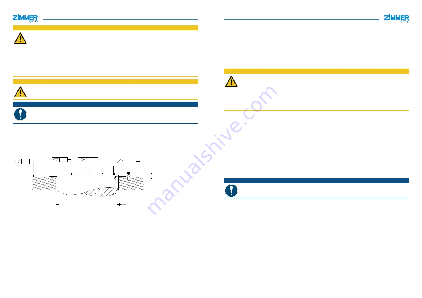
The product must be installed on an appropriate mounting surface in accordance with the levelness and total run-out
specifications.
Ö
Permissible unevenness and total run-out of < 0.02 mm
Ö
Make sure the mounting surface is sufficiently rigid and flat.
0.02
0.01 A
A
0.02
0.01 A
A
bstimmmaß
►
Adjust the shim
bn
to the specified adjustment dimension.
Ö
Refer to the laser marking on the product for the adjustment dimension.
►
Check whether all cutting rings and O-rings are properly inserted in the product.
► Remove the sealing plugs from the hydraulic connections A
5
and bleed connection C
6
.
► Set the product onto the
bn
shim
and mounting piece
bm
.
Ö
Ensure that the hydraulic connection A
5
and
the bleed connection C
6
sit on the spotfaces.
►
Loosely attach the housing
1
and
shaft connection
8
using the mounting screws
bl
to the mounting piece
bm
and
shim
bn
.
CAUTION
Under no circumstances may the product be pressurized before all screws are tightened with the necessary
tightening torque.
Ö
Screw-in depth = at least 1.2. x Ø
Ö
The mounting screws are not included in the scope of delivery.
Ö
Strength class of the mounting screws at least 12.9
Ö
DIN EN ISO 4762.
Ö
The product is centered via the screw fittings.
Ö
Maximum tolerance of the shim ± 5 µm.
►
Tighten the mounting screws
bl
with the specified tightening torque to the mounting piece
bm
.
►
Tighten the mounting screws
bl
on the housing first, then on the shaft connection.
► Observe the tightening torques of the mounting screws
bl
.
►
Tighten the mounting screws
bl
crosswise.
►
Bleed the product by flushing it with hydraulic oil HLP46.
Ö
Hydraulic connection A = Pressurization
Ö
Bleed connection C = Venting
►
Add hydraulic oil to the product at low pressure using hydraulic connection A
5
► Flush the product until the hydraulic oil escapes from the bleed connection C
6
.
► Seal the bleed connection C
6
at mounting piece
bm
using a suitable pressure-resistant closure.
► Carry out a functional check.
Ö
The procedure of the functional test is described in section "Function check".
NOTICE
Non-compliance may result in material damage.


