ZIO, Motherboard User Manual
Rev. 2.0
Zilogic Systems
Page 15
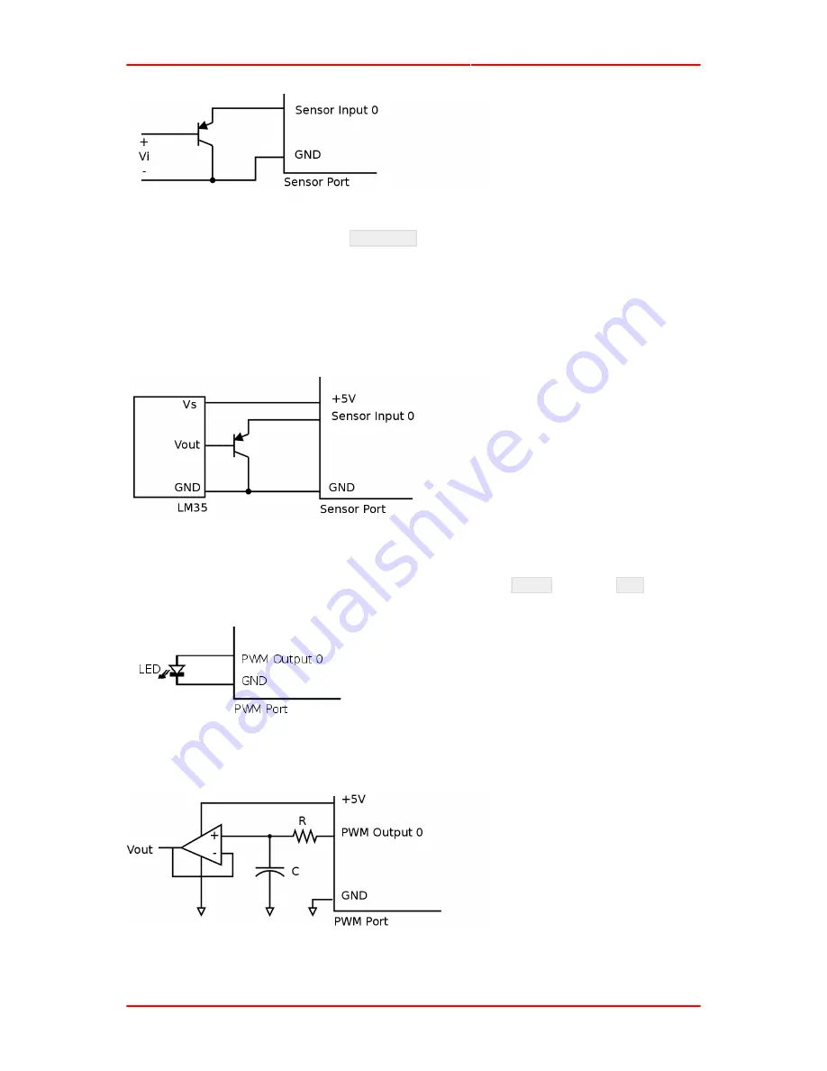
This is a PNP emitter follower, where the emitter voltage is almost equal to the base voltage. For
a V
i
range of 0 to 4.4V, the voltage at
Sensor 0
is (V
i
+ 0.6). To compensate for the added 0.6V,
subtract 0.6 to the obtained voltage.
Temperature Sensor.
The LM35 is an example of an non-resistive sensor. The LM35 produces a
voltage that is proportional to the temperature. The voltage output by the LM35, increases by 10mV
for every degree Celsius rise in temperature. As the temperature changes from 2
o
C to 150
o
C, the
voltage rises from 0V to 1.5V. The LM35 can be connected to the Sensor port using the transistor
buffer and is shown in the following circuit.
5. PWM Port
LED Brightness Control.
An LED can be connected between the
PWM N
signal and
GND
as shown
in the following diagram. When the duty cycle is varied the LED brightness varies accordingly.
One Bit DAC.
An analog output can be generated from the PWM signal, using a low pass filter
circuit. The low pass filter circuit with an op-amp buffer is shown in the following diagram.
If the analog output has a frequency of F, the PWM frequency should be much higher than F. The
values of R and C are given by the following formula.


