ZILMET USA
400 Frenchtown Road - East Greenwich, RI 02818 – phone 401 884 4943
INSTRUCTIONS FOR INSTALLATION AND OPERATION OF ZILMET USA EXPANSION TANKS
PROFESSIONAL INSTALLATION REQUIRED
rev
. Sep
20
20
page 3 / 7
4.
GENERAL INSTRUCTIONS FOR INSTALLATION
Inspect the product for any damage that may have occurred during shipping. If evident damage is detected, notify the freight carrier and
reseller immediately, and do not install the tank.
PRIOR TO INSTALLATION OF THE TANK
1.
Ensure that access to the installation area is restricted. Do not install where children are present or may be present.
2.
Use caution and always wear protective gloves and safety goggles during installation and maintenance of the expansion tank. Use suitable
and
appropriate lifting tools when positioning and installing the tank.
3.
Choose an appropriate site for installation which is enclosed and well aerated
. The tank must be placed far from heat
sources,
electric
generators and any other element that may damage the tank. Install in an area that allows for easy access and inspection of the tank.
4.
Depending on the model, the weight of the expansion tank filled with water can be supported by the system piping. To avoid overloading the
pipes
and possibly breaking or offsetting the pipe connections, it is important that the piping is supported by suitable bracing (strapping, hanger,
brackets).
If the tank does not have a support base, and is installed horizontally, it must be properly supported along the entire length of the tank.
5.
Before using any Zilmet accessory to hang the expansion vessel on a wall, check that the wall itself can sustain the weight of a full
expansion
vessel, as it will fill with system liquid. This will add considerable weight to the tank during normal operation.
6.
Before installing the expansion tank, remove the plastic cap on the air valve of the tank and using a controlled manometer verify that it has
the
correct factory set pre-charge (with a tolerance of ± 20%). Adjust the tank pre-charge to the required value (
do not over-pressurize
) and
replace
and tighten the plastic cap on the air valve. Only adjust the tank when empty of water
and the system connection open to atmosphere
.
7.
Install the tank at the point specified by the system design, specifications and instructions, preferably in a vertical position
for diaphragm cycle
symmetry to result in optimum product life
. I
f tank is to be installed horizontally, then it must be fully supported independent from the piping. I
nstall the
tank in the following places:
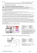
INSTALLATION IN CLOSED HYDRAULIC HEATING (HYDRONIC) SYSTEMS
A = Draining
B = Safety valve
C = Air bleed valve
D = Gate valve
E = Backflow preventer
F = Manometer
G = Pump
H = Utilities
I = Mixing valve
L = Expansion tank
M = Boiler
ONLY QUALIFIED AND LICENSED PERSONNEL MAY PERFORM INSTALLATION.
DO NOT ACCESS WHILE UNDER PRESSURE. DANGER OF SCALDING, BURSTING OR WATER DAMAGE.
BEFORE INSTALLING, THE SYSTEM (INCLUDING THE TANK) MUST BE SHUT OFF, COOLED AND NOT PRESSURIZED, ALL
OF THE ELECTRICAL PARTS MUST BE UNPLUGGED AND THE TANK MUST BE COMPLETELY EMPTY.
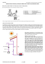
INSTALLATION OF THERMAL EXPANSION TANKS IN SYSTEMS FOR THE PRODUCTION OF
POTABLE
HOT WATER
A = Draining
B = Safety valve
C = Air bleed valve
D = Gate valve
E = Backflow preventer
F = Manometer
G = Shutoff valve
H = Utilities
I = Mixing valve
L = Expansion tank
M = Water heater
•
The tank must be installed on the runback piping. An alternative
location may be on the supply side, provided that the maximum
working pressure and temperature limits are kept.
•
The use of proper anti-scale and corrosion inhibitors additives is
required in hydronic systems; when necessary, also the use of
a proper anti-freeze fluid (glycol) must be considered.
•
If tank is to be installed horizontally, then it must be fully
supported independent from the piping.
•
The tank must be
i
nstalled on the
cold water supply side to
the water heater.
•
If tank is to be installed horizontally, then it must be fully
supported independent from the piping.


