background image

Construction manual RasPiBox Zero Rev A

6.) Assemble Diode D5

Pls Note: D5 has no polarity!

7.) Assemble the switching regulator IC (IC2)

11 of 18

Pin 1

D5

Pin 1

Summary of Contents for RasPiBox Zero Lite

Page 1: ...Construction manual RasPiBox Zero Rev A RasPiBox Zero Lite Version 2 1 construction manual Rev Date Description A 02 09 16 First release 1 of 18 ...

Page 2: ...Construction manual RasPiBox Zero Rev A Tools agregulated soldering iron 25 40W with small tip a wet sponge to clean the tip thin solder wire Side cutting pliers 2 of 18 ...

Page 3: ...Construction manual RasPiBox Zero Rev A Needle nose pliers Medium cross slot screwdriver 3 of 18 ...

Page 4: ...nstruction manual RasPiBox Zero Rev A Parts Basic Version 3x 2pole terminal block K2 K6 K8 1x 2x20pole female header K1 2x din rail holders 2x self tapping screws 1x Schottky diode MBRS140 4 of 18 cathode ...

Page 5: ...nd the terminal blocks they re grey or blue and come in 2 pin shapes We ll need to slide two 2 pin blocks together 2 Place and solder terminal blocks We ve to put the blocks into the proto plate Make sure you place them so that the open ends are facing out as shown 5 of 18 ...

Page 6: ...Construction manual RasPiBox Zero Rev A 3 Assemble and solder the 40 pole socket We ve to place and solder the 2x20 pin socket for the Raspberry Pi 4 Place and solder the schottky diode 6 of 18 cathode ...

Page 7: ...e set this jumper in the basic version only You can supply the PiZero with 5V DC directely from the terminal K2 now Perform the next steps only if you have the standard kit includes the parts of the voltage regulator and USB socket Otherwise continue with step 16 7 of 18 Set the soldering jumper ...

Page 8: ...d Version 1x capacitor 100nF C13 1x Electrolytic capacitor 220uF 35V C11 1x Tantal capacitor 68uF C12 1x suppressor diode SM6T39CA code GP608 D3 1x switching regulator IC LM2675 IC2 1x Schottky diode MBRS140 code pH21 D1 1x inductor 330uH L1 1x USB A socket K3 8 of 18 ...

Page 9: ...Construction manual RasPiBox Zero Rev A Power supply circuit 9 of 18 ...

Page 10: ...Construction manual RasPiBox Zero Rev A Placement 10 of 18 L1 D1 C12 IC2 D3 D5 C13 ...

Page 11: ...Construction manual RasPiBox Zero Rev A 6 Assemble Diode D5 Pls Note D5 has no polarity 7 Assemble the switching regulator IC IC2 11 of 18 Pin 1 D5 Pin 1 ...

Page 12: ...Construction manual RasPiBox Zero Rev A 8 Assemble the capacitor C13 9 Assemble the schottky diode D1 12 of 18 cathode ...

Page 13: ...Construction manual RasPiBox Zero Rev A 10 Assemble the tantal capacitor C12 13 of 18 ...

Page 14: ...he inductance and pads Depending from the situation on the market we equip the kits with different inductors Some of them need a special preparation preparation needed no preparation needed 11 1 add solder to the coil 11 2 add solder to the pcb 14 of 18 ...

Page 15: ...Construction manual RasPiBox Zero Rev A 12 Assemble the inductance L1 13 Assemble the electrolytic capacitor C11 15 of 18 ...

Page 16: ...ble the USB socket K3 option 15 Connect the USB port It s very important that the wires for D and D have exactely the same length The optimal length for the cables is 6 7 cm pcb PiZero Vcc PP1 D PP23 D PP22 A ground connection is not needed 16 of 18 ...

Page 17: ...Construction manual RasPiBox Zero Rev A 16 Mount the pcb into the bottom shell 17 Mount the 2 holders for the din rail Please take care to mount the holder from the inner channel to the outside 17 of 18 ...

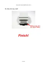
Page 18: ...Construction manual RasPiBox Zero Rev A 18 Mount the top shell Finish 18 of 18 Milling on top side sd card of PiZero ...

Reviews: