U-EK230E
L-BAL-E185-GB 2023/10 Index 005
11660-0711-03
4/12
7
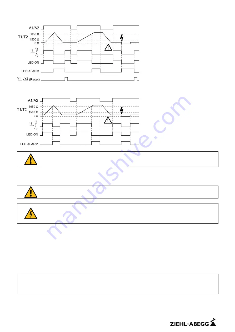
Function diagram
Caution! The device switches on automatically after a supply voltage dip.
Inputs (Y1/Y2) bridged
With a bridge at the reset input (Y1/Y2) the reclosing lock is out of operation. The
device switches back automatically, when the temperature of the thermistor
circuit has fallen below the switchback value.
8
Important notes
Attention!
Observe safety rules and standards. Notice safety remarks!
Attention!
Hazardous voltage!
May cause electric shock and burns.
Before commencing work on the system, the power must be disconnected.
9
Installation
•
The applicant must observe safety rules and standards.
•
The device can be mounted on 35 mm rail according EN 60715 or with screws M4 (Option).
•
Design V2, width 35 mm (2 M).
•
The device must be installed in an enclosure of class IP 5X or better.
•
Terminals maximum tightening torque 0.5 Nm.
When installing the device into the switchgear cabinet, please observe the max. permissible
temperature. Care for both, sufficient clearance to other devices or sources of heat or enough
forced draught. If cooling is made more difficult, e.g. close devices with increased surface
temperature or by handicap of airflow cooling, the permissible ambient temperature reduces.


