


5.6 Analog input (0 - 10 V, 2 - 10 V / 10 - 0 V, 10 - 2 V)
The device has an analog input for setting fan speed.
Terminals
“
E1
”
/
“
GND
”
(Analog In 1).
Ensure correct polarity!
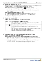
Over DIP 4 an inverting of the input is possible
•
DIP 4 =
|
OFF
|
(factory setting) for signals: 0 - 10 V, 2 - 10 V
•
DIP 4 =
|
ON
|
for signals: 10 - 0 V, 10 - 2 V
Attention!
Never apply line voltage to analog inputs!
5.7 Output voltage 0 - 10 V (A1 = Analog Out 1)
Connection to terminals
“
A1
”
-
“
GND
”
=
“
Analog Out 1
”
(I
max
10 mA).
It is not permissible to connect outputs of several devices to each other!
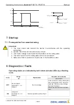
The function of the signal output A1 (Analog Out 1) can be determined by
DIP8.
DIP 8 =
|
OFF
|
Constant v 10 V for external potentiometer (factory setting)
DIP 8 =
|
ON
|
0 - 10 V
modulation 0 - 100 %
•
Proportional the internal control of modulation with consideration
“
n-min
”
and
“
n-max
”
setting.
•
For enable
“
OFF
”
it goes
not back to
“
0 V
”
.
•
For motor fault the output signal remains for a slave controller (
“
Master-
Slave
”
combination).
5.8 Voltage supply for external devices (+24V, GND)
A voltage supply is integrated for external devices e.g. a sensor (max. current load see
technical data).
In case of overload or short circuit (24 V
–
GND), the external power supply is shut down
(multi-fuse). The device performs a
“
Reset
”
and continues operation.
•
It is not permissible to connect voltage outputs of several devices to each other!
•
It is not permissible to connect voltage outputs in the device to each other!
Operating Instructions
Acontrol
PSET6 / PSET10
Electrical installation
L-BAL-E141-GB 1925 Index 004
Part.-No.
13/24


