4
11
4.
Connecting the cable
-
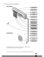
Indoor unit
Connect the power cable to the indoor unit by connecting
the cables to the units to the clamps on the terminal board
in the correct sequence. The colours of the wires and the
reference on the clamps must correspond.
Note: In some models, the cover must be removed in order
to connect the wiring.
-
Outdoor unit
1.
Remove the access cover of the unit by loosening the
screw. Connect the wires to the clamps on the terminal
board in the following manner:
2.
Connect the power cable to the terminal board.
3.
Replace the cover and tighten the screw.
4.
Place an approved circuit breaker between the power
source and the unit for model S1170. Install a suitable
main switch.
The illustrations are based on standard models.
The air conditioner you have purchased may be a different model.
Warning:
1.
Always connect the air conditioner to a separate power circuit. Refer to the diagram on the inside of
the access cover for the connection of the wires.
2.
Check that the cable thickness conforms to regulations (see table below).
3.
Check that all wiring is securely connected.
4.
Install an earth leak switch.
Note: All cables used must be approved in accordance with local regulations.
Cable specifications
Terminal board
(inside)
Front panel
Base plate
Access cover for
terminal board
(inside)
Outdoor unit
Indoor unit
Housing
Type
Cross-section
Type
Cross-section
Type
Cross-section
Power cable
Power cable connection
Power cable connection 1 (heat pump)
S1126
S1135
S1153
S1170


