Install the MXK
32
MXK Hardware Installation Guide
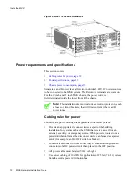
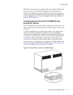
Figure 9: MXK 319 chassis dimensions
Power requirements and specifications
This section covers:
•
Cabling rules for power, page 32
•
•
Chassis power consumption, page 33
Separate A and B power feeds allow two individual –48V DC power sources
to be connected to the MXK system. The Return (+) terminals are common.
For the 19 inch and 23 inch MXK chassis, the power wiring is
field-terminated inside the lower front of the chassis.
Note:
The installation site must include overcurrent protection, such
as fuses or circuit breakers, that will limit current at the A and B
power inputs.
Cabling rules for power
Following are power cabling rules applicable to the MXK system.
•
Provide an appropriate disconnect device as part of the building
installation for systems such as the MXK that receive power from an
external, auxiliary, or emergency source. When power is routed from a
power distribution frame, the disconnect device can be used as a power
cutoff (for example, an ON/OFF switch or breaker).
•
Connect all disconnect devices so that they disconnect all ungrounded
conductors of a DC power circuit when placed in the OFF position.
•
All power cables must be rated VW-1 or higher.
•
Use power cabling of 10 AWG for applications of 25 feet (7.62 m) or less
from the central power distribution bus.


