TROUBLESHOOTING
Page B11-3
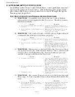
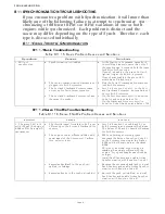
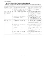
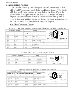
B11-2.2Servo Throttle Troubleshooting
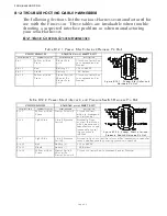
B11-2.3Servo Clutch Troubleshooting
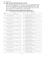
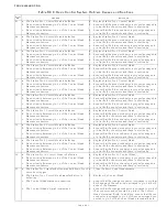
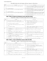
Table B11-19: Servo Throttle Problem Causes and Solutions
System
Causes
Solutions
1. One or both of the
engines continually
changes RPM. Will not
synchronize properly.
a. A Control Head’s Command Signal is vary-
ing.
a. Scroll to the Diagnostic Menu Function
Code H0. Go to the appropriate Station A/
D Count’s display. The Value should not
change by more than +/- 1 A/D Count. If
so, check the connections and if good,
replace the Control Head.
b. The engine(s) is not running smoothly.
b. Increase the engines’ RPM’s in Warm-up
Mode. Scroll to Function Code H0 and dis-
play the Tach Sender’s input frequency.
If the frequency is varying, check the push-
pull cable for movement.
If the push-pull cable is not moving, swap
the Port and Starboard Tach Senders.
If the frequency still varies on the same
side, the engine needs servicing.
c. Defective Tach Sender
c. Same procedure as b. However, if the fre-
quency variations move to the opposite
side, replace that Tach Sender.
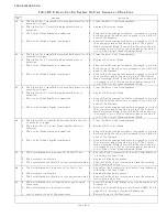
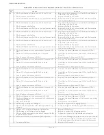
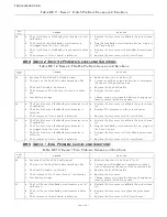
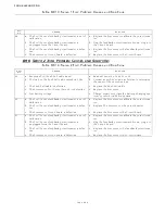
Table B11-20: Servo Clutch Problem Causes and Solutions
System
Causes
Solutions
1. Will not
synchronize.
a. The Processor(s) think Astern is being
commanded.
a. Place both the Port and Starboard Proces-
sors into Warm-up Mode by pressing the
transfer button while moving the Control
Head levers to the Ahead detent. Both red
LED’s on the Control Head should be
blinking.
If not, reverse the wires at pins 5 and 7 at
the Control Head. Change the Clutch
direction with Function Code C5.
Summary of Contents for ClearCommand 9000 Series
Page 132: ......
Page 133: ...APPENDIX A...
Page 134: ......
Page 139: ......
Page 140: ...Page A 4...
Page 143: ......
Page 144: ...10...
Page 148: ...Page A 18...
Page 149: ...Page A 19 TEMPLATE...
Page 150: ...Page A 20...
Page 152: ...Page A 22...
Page 154: ...Page A 24...
Page 156: ...Page A 26...
Page 157: ...Page A 27 Drawing 11488D 1 Twin Screw Single APS Connection Alternate Remote Switch...
Page 158: ...Page A 28...
Page 159: ...Page A 29 Drawing 11488D 2 Twin Screw Dual APS Connections...
Page 160: ...Page A 30...
Page 161: ...Page A 31 Drawing 11488D 3 APS Notes Page...
Page 162: ...Page A 32...
Page 164: ...Page A 34...
Page 166: ...Page A 36...
Page 170: ...Page A 40...
Page 172: ...Page A 42...
Page 176: ...Page A 46...
Page 178: ...Page C 48 ZF Mathers LLC 12125 Harbour Reach Drive Suite B Mukilteo WA 98275...
Page 179: ...APPENDIX B...
Page 180: ......
Page 234: ...Appendix B 6...
Page 238: ...Appendix B 10...
Page 242: ...Appendix B 14...
Page 247: ...Service Field Test Unit Reference Manual MM13927 Rev E 4 07...
Page 248: ......
Page 250: ...Page ii Table of Contents...
Page 264: ...SERVICE FIELD TEST UNIT MM13927 RvD 10 03 Page 3 2...
Page 265: ...APPENDIX C...
Page 266: ......
Page 267: ...Appendix C 1 Drawing 12284A 1 ClearCommand Diagram all options...
Page 268: ...Appendix C 2...
Page 269: ...Appendix C 3 Drawing 12284A 2 ClearCommand Circuit Board Connections...
Page 270: ...Appendix C 4...
Page 271: ...Appendix C 5 Drawing 12284A 3 ClearCommand Drawing Notes Page...
Page 272: ...Appendix C 6...


