Page A-23
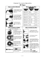
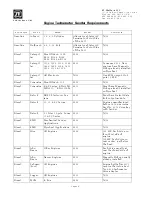
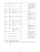
Deutsch Connector Assembly
DT Type
Wire Gauge
Range
Strip Length
(inches)
Contact Part
Number
0460-202-20141
20 AWG
.156-.218
0462-201-20141
20 AWG
.156-.218
0460-202-16141
16, 18 & 20 AWG
.250-.312
0462-201-16141
16, 18 & 20 AWG
.250-.312
0460-215-16141
14 AWG
.250-.312
0462-209-16141
14 AWG
.250-.312
0460-204-12141
12 & 14 AWG
.222-.284
0462-203-12141
12 & 14 AWG
.222-.284
0460-204-08141
8 & 10 AWG
.430-.492
0462-203-08141
8 & 10 AWG
.430-.492
0460-204-0490
6 AWG
.430-.492
0462-203-04141
6 AWG
.430-.492
1. Grasp crimped contact
approximately (25.2 mm) one
inch behind the contact barrel.
2. Hold connector with rear
grommet facing you.
3. Push contact straight into
connector grommet until a click
is felt. A slight tug will confirm
that contact is properly locked
in place.
4. Once all contacts are in place,
insert wedgelock with arrow pointing
toward exterior locking mechanism.
The wedgelock will snap into place.
Rectangular wedges are not oriented.
They may go in either way.
NOTE: The receptacle is shown –use the
same procedure for plug.
Step 1: Contact Removal
Step 4: Contact Insertion
Step 2: Wire Stripping
1. Remove wedgelock using
needlenose pliers or a hook
shaped wire. Pull wedge
straight out.
2. To remove the contacts,
gently pull wire backwards,
while at the same time
releasing the locking finger
by moving it away from the
contact with a screwdriver.
3. Hold the rear seal in
place, as removing the
contact may displace the
seal.
(800) 223-1236
Solid Contacts
Step 3: Contact Crimping
5. Insert wire into contact.
Contact must be centered
between indicators. Close
handles until crimp cycle is
completed.
6. Release handles and remove
crimped contact.
1. Strip insulation from wire.
(See Step 2).
2. Raise selector knob and
rotate until arrow is aligned with
wire size to be crimped.
3. Loosen locknut, turn adjust-
ing screw in until it stops.
4. Insert contact with barrel up.
Turn adjusting screw counter–
clockwise until contact is flush
with indentor cover. Tighten
locknut.
7. Inspect terminal to ensure
that all strands are in crimp
barrel.
NOTE:
Tool must be
readjusted for each type/size
of contact. Use HDT04-08 for
size 8 and 4 contacts.
Use Crimp Tool #HDT48-00
Summary of Contents for ClearCommand 9000 Series
Page 132: ......
Page 133: ...APPENDIX A...
Page 134: ......
Page 139: ......
Page 140: ...Page A 4...
Page 143: ......
Page 144: ...10...
Page 148: ...Page A 18...
Page 149: ...Page A 19 TEMPLATE...
Page 150: ...Page A 20...
Page 152: ...Page A 22...
Page 154: ...Page A 24...
Page 156: ...Page A 26...
Page 157: ...Page A 27 Drawing 11488D 1 Twin Screw Single APS Connection Alternate Remote Switch...
Page 158: ...Page A 28...
Page 159: ...Page A 29 Drawing 11488D 2 Twin Screw Dual APS Connections...
Page 160: ...Page A 30...
Page 161: ...Page A 31 Drawing 11488D 3 APS Notes Page...
Page 162: ...Page A 32...
Page 164: ...Page A 34...
Page 166: ...Page A 36...
Page 170: ...Page A 40...
Page 172: ...Page A 42...
Page 176: ...Page A 46...
Page 178: ...Page C 48 ZF Mathers LLC 12125 Harbour Reach Drive Suite B Mukilteo WA 98275...
Page 179: ...APPENDIX B...
Page 180: ......
Page 234: ...Appendix B 6...
Page 238: ...Appendix B 10...
Page 242: ...Appendix B 14...
Page 247: ...Service Field Test Unit Reference Manual MM13927 Rev E 4 07...
Page 248: ......
Page 250: ...Page ii Table of Contents...
Page 264: ...SERVICE FIELD TEST UNIT MM13927 RvD 10 03 Page 3 2...
Page 265: ...APPENDIX C...
Page 266: ......
Page 267: ...Appendix C 1 Drawing 12284A 1 ClearCommand Diagram all options...
Page 268: ...Appendix C 2...
Page 269: ...Appendix C 3 Drawing 12284A 2 ClearCommand Circuit Board Connections...
Page 270: ...Appendix C 4...
Page 271: ...Appendix C 5 Drawing 12284A 3 ClearCommand Drawing Notes Page...
Page 272: ...Appendix C 6...

