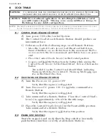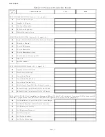
DOCK TRIALS
Page6-3
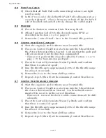
6-8 T
HROTTLE
P
AUSE
F
OLLOWING
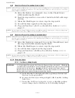
S
ERVO
S
HIFT
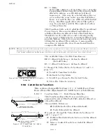
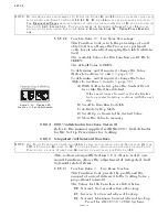
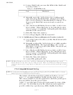
A) Move the Station in command’s lever to the Ahead detent,
while monitoring the Shaft.
B) Start the stop-watch as soon as the Clutch Push-Pull cable stops
moving.
C) When the Shaft begins to rotate, stop the stop-watch.
D) Record the time expired on the stop-watch.
E) Program Function Code E5 as described in Section 5-5.2.6.1,
page 5-8
.
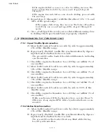
6-9 T
HROTTLE
P
AUSE
F
OLLOWING
S
OLENOID
S
HIFT
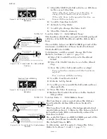
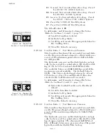
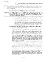
A) Move the Station in command’s lever to the Ahead detent, start
the stop-watch while monitoring the Shaft.
B) When the Shaft begins to rotate, stop the stop-watch.
C) Record the time expired on the stop-watch.
D) Program Function Code
E5
as described in Section 5-6.2.1.1,
page 5-10.
6-10 T
ROLLING
V
ALVE
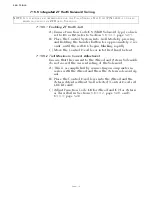
6-10.1 Troll Servo Adjustments
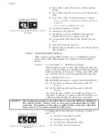
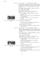
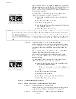
A) Verify that the Troll Push-pull cable is positioned at the Full
Pressure (Lock-up) position.
B) If connected, disconnect the push-pull cable from the Trolling
Valve lever.
C) Secure the Troll lever using wire or rope so that the position
cannot change due to vibration or if accidentally bumped.
NOTE: A T
EST
C
ONTROL
H
EAD
AND
A
STOP
-
WATCH
ARE
RECOMMENDED
TO
DETERMINE
THE
CORRECT
SETTING
FOR
THE
T
HROTTLE
P
AUSE
. I
F
A
T
EST
C
ONTROL
H
EAD
IS
NOT
AVAILABLE
,
A
SECOND
PERSON
MAY
BE
NEEDED
.
NOTE: I
F
THE
TIME
RECORDED
IN
S
ECTION
6-8,
STEP
D)
EXCEEDS
5.0
SECONDS
,
A
C
LUTCH
P
RESSURE
I
NTERLOCK
IS
REQUIRED
. R
EFER
TO
S
ECTION
8-2,
PAGE
8-2.
NOTE: A T
EST
C
ONTROL
H
EAD
AND
A
STOP
-
WATCH
ARE
RECOMMENDED
TO
DETERMINE
THE
CORRECT
SETTING
FOR
THE
T
HROTTLE
P
AUSE
. I
F
A
T
EST
C
ONTROL
H
EAD
IS
NOT
AVAILABLE
,
A
SECOND
PERSON
MAY
BE
NEEDED
.
NOTE: I
F
THE
TIME
RECORDED
IN
S
ECTION
6-9,
STEP
D)
EXCEEDS
5.0
SECONDS
,
A
C
LUTCH
P
RESSURE
I
NTERLOCK
IS
REQUIRED
. R
EFER
TO
S
ECTION
8-2,
PAGE
8-2.
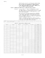
WARNING:
I
T
IS
PREFERABLE
TO
ADJUST
THE
T
ROLLING
V
ALVE
DURING
SEA
TRIALS
. H
OWEVER
,
IN
SOME
CASES
ADJUSTMENT
OF
T
ROLL
M
INIMUM
P
RESSURE
(L2)
CAN
BE
ACCOM
-
PLISHED
WHILE
AT
THE
DOCK
. D
O
N
OT
ATTEMPT
TO
MAKE
ANY
T
ROLL
ADJUST
-
MENTS
UNLESS
THE
DOCK
AND
THE
MOORING
LINES
ARE
CAPABLE
OF
SECURING
THE
VESSEL
WITH
FULL
THRUST
FROM
AT
LEAST
ONE
SCREW
.
Summary of Contents for ClearCommand 9000 Series
Page 132: ......
Page 133: ...APPENDIX A...
Page 134: ......
Page 139: ......
Page 140: ...Page A 4...
Page 143: ......
Page 144: ...10...
Page 148: ...Page A 18...
Page 149: ...Page A 19 TEMPLATE...
Page 150: ...Page A 20...
Page 152: ...Page A 22...
Page 154: ...Page A 24...
Page 156: ...Page A 26...
Page 157: ...Page A 27 Drawing 11488D 1 Twin Screw Single APS Connection Alternate Remote Switch...
Page 158: ...Page A 28...
Page 159: ...Page A 29 Drawing 11488D 2 Twin Screw Dual APS Connections...
Page 160: ...Page A 30...
Page 161: ...Page A 31 Drawing 11488D 3 APS Notes Page...
Page 162: ...Page A 32...
Page 164: ...Page A 34...
Page 166: ...Page A 36...
Page 170: ...Page A 40...
Page 172: ...Page A 42...
Page 176: ...Page A 46...
Page 178: ...Page C 48 ZF Mathers LLC 12125 Harbour Reach Drive Suite B Mukilteo WA 98275...
Page 179: ...APPENDIX B...
Page 180: ......
Page 234: ...Appendix B 6...
Page 238: ...Appendix B 10...
Page 242: ...Appendix B 14...
Page 247: ...Service Field Test Unit Reference Manual MM13927 Rev E 4 07...
Page 248: ......
Page 250: ...Page ii Table of Contents...
Page 264: ...SERVICE FIELD TEST UNIT MM13927 RvD 10 03 Page 3 2...
Page 265: ...APPENDIX C...
Page 266: ......
Page 267: ...Appendix C 1 Drawing 12284A 1 ClearCommand Diagram all options...
Page 268: ...Appendix C 2...
Page 269: ...Appendix C 3 Drawing 12284A 2 ClearCommand Circuit Board Connections...
Page 270: ...Appendix C 4...
Page 271: ...Appendix C 5 Drawing 12284A 3 ClearCommand Drawing Notes Page...
Page 272: ...Appendix C 6...

