Warning:
Charge ended by BMS
If the EVMS detects an error, this warning page
will be displayed. In most cases, the error can be
acknowledged/reset by pressing Select. For a full list of
errors you might see, refer to section
Error Detection
.
Reset SoC
Enter Setup
Display Off
Exit Options
You can bring up this options menu by holding your
finger down for 1 second. From here you can enter the
Setup mode, or switch the display off. (Note that Reset
SoC only works with EVMS Core.)
When the display is off, touch and hold anywhere for
1 second to turn it back on. Display will automatically
wake if there is a new warning to display.
Setup mode can only be entered from Idle state, i.e
when the vehicle is not charging or being driven.
Configuring Settings
The EVMS Monitor can be used to configure settings for all devices on the CAN bus.
EVMS: Setup
General Settings
Parameter:
BMS: Undervoltage
Value:
2.50V
Exit Setup
<
<
<
>
>
>
The Setup mode has three rows. The top row
toggles between the General Settings and the Pack
Configuration sections. Tap the arrows either side to
nagivate between these. In the General Settings page,
the second row selects the parameter to be modified,
and the third row modifies the parameter itself.
The Exit Setup button will distribute new settings
to all devices on the network then return to normal
operation.
EVMS: Setup
Pack Configuration
Module ID:
0
Num cells:
12
Exit Setup
<
<
<
>
>
>
This is the page for configuring your battery pack, so
the BMS knows how many cells to monitor.
Tap the arrows either side of the Module ID row to
select the module in question, and the arrows either
side of Num cells is used to modify how many cells
that BMS module should expect.
List of settings - EVMS Lite
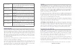
The following table describes the parameters available in the General Settings page.
Name
Range
Description
BMS: Min voltage
0 - 5.00V
Adjusts the low voltage warning threshold for
each cell in your traction pack.
BMS: Max voltage
0 - 5.00V
Adjusts the high voltage warning threshold for
each cell in your traction pack.
BMS: Shunt voltage
3.00 - 5.00V
Adjusts the voltage at which shunt balancers
turn on for each cell in the tracion pack.
BMS: Low temp warn
0-100˚C
The EVMS can provide a warning if any BMS
modules report a temperature below or above
these respective thresholds.
BMS: Overtemp warn
0-100˚C
Stationary Mode
YES/NO
Switches the EVMS into Stationary Mode,
for battery backup and off-grid power type
applications. Please refer to “Stationary
Applications” Section for more information.
Display brightness
0-100%
Adjusts the brightness of the LCD display’s
backlight.
Display fade delay
0-20sec
Changes the length of time the display will
remain lit after a button press, change of state or
warning notification.
Buzzer On
YES/NO
Selects whether the Monitor should sound the
buzzer for alerts. (Safest to leave this on.)
Use Fahrenheit
YES/NO
Changes display of temperature units to
Fahrenheit instead of Celcius.
Error Detection
The EVMS monitors a wide range of operating parameters for your electric vehicle and can
notify you if any exceed their safe range or any faults are detected. In most cases, errors
can be acknowledged/reset by pressing the Select button. Critical errors are responded to
automatically (such as by shutting down the traction circuit due to a critically low cell),
while others are at the driver’s discretion to respond to (such as over-temperature warnings).
The following table describes the errors you may encounter.
Error
Description


