


Appendix D. CPS Menu Structure
Start by entering a Custom Call number between 1 and 255 (or use the
UP
and
DOWN
ARROW
keys to select a previously defined call) and press
ENTER
. Enter the requested
frequency and duration parameters for each tone, the duration between the tones, and the talk
time (described above). After the talk time has been entered, the program will return to the
Custom Call number entry window. Enter a new call number to define another Custom Call
or press
ESC
to return to the SYSTEM CONFIGURATION menu. To specify a Custom Call
page, enter the leading digit followed by the desired Custom Call number.
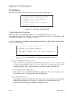
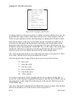
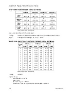
For example, assuming the “Custom Call” paging format has been assigned to leading digit
“C”, keying “C11” on the Model 4010 paging/DTMF keypad would enter the custom call
shown in Figure D2-55 on the paging stack. To then transmit the stacked page(s) on the
selected channel(s), press the “PAGE SEND” key.
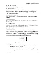
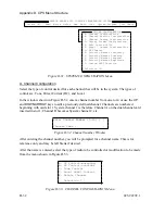
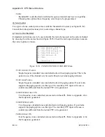
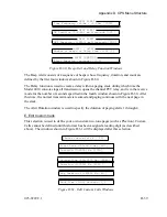
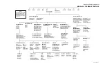
F. Input/Output Configuration
This function is used to create and name auxiliary inputs and outputs used in the console, and
to set the mode of the Spare/Aux. Ports on the Model 4010 main PC board (see Figure D-62).
Port numbers 1-8 are assigned to standard main PC board Spare/Aux. Ports. Port numbers 9-
38 are assigned to any optional Expanded Aux. I/O Card(s) in the Model 4010 console.
A. Auxiliary Inputs
B. Auxiliary Outputs
C. Spare Input / Output Mode
Selection [A]
Figure D-62. INPUT/OUTPUT Menu
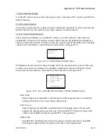
1) Auxiliary Inputs
Up to 38 auxiliary input ports may be created and named (or modified) with this selection.
Before an input port can be referenced in other areas of CPS, it must be defined. You will be
prompted for input port numbers and optional associated names. Note that Input Ports 1-8
can be defined only if the main PC board Spare/Aux. Inputs (on connector P8) have been
defined as “Aux-Inputs” via selection C from the menu shown in Figure D-62.
2) Auxiliary Outputs
Up to 38 auxiliary output ports may be created and named (or modified) with this selection.
Before an output port can be referenced in other areas of CPS, it must be defined. You will
be prompted for output port numbers and optional associated names. Note that output Ports
1-8 can be defined only if the main PC board Spare/Aux. Outputs (on connector P7) have
been defined as “Aux-Outputs” via selection C from the menu shown in Figure D-62.
3) Spare Input/Output Mode
Use this selection to define the mode of the main PC board Spare/Aux. Inputs and Outputs.
The next window will allow you to define the mode of each port (input and output)
separately.
D-40
025-9229C.1
Summary of Contents for 4010
Page 2: ......
Page 4: ......
Page 7: ...1 INTRODUCTION HARDWARE REQUIREMENTS 1 1 DEFINITIONS 1 1 MANUALS 1 2...
Page 8: ......
Page 12: ......
Page 16: ...Section 2 Installation 2 4 025 9229C 1...
Page 18: ......
Page 34: ...Section 3 Tutorial 3 16 025 9229C 1...
Page 36: ......
Page 58: ......
Page 60: ......
Page 62: ......
Page 64: ......
Page 108: ...Appendix D CPS Menu Structure D 44 025 9229C 1...
Page 110: ......


