Console Installation
22
latches on the back of the console and lifting the top open. The rack-mount console has
two screws that hold the top cover on located on the back of the unit.
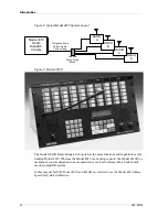
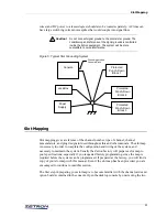
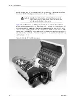
shows the view of the desktop console with the top opened. You will notice
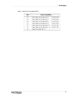
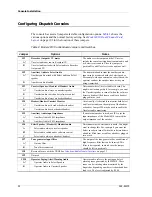
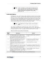
several card slots designated J6-J12. Since the system is tested at the Zetron factory, you
will find the channel cards already plugged into the assigned slots. Slots J12-J7 are for
channel cards or Auxiliary I/O boards. J6 is for the Phone Patch card. On the back of the
unit are three 50-conductor male Amphenol-type plugs used to connect the Console to the
punch-down blocks and radios. These are designated J4 (channels 1-4), J3 (channels 5-8),
and J2 (channels 9-12).
Figure 6: A Model 4010 with its case open
Caution!
Keep the front of the desktop unit on the tabletop, do not let
the front hang over a table edge. The console can be knocked
off balance onto the floor in this position.
!

