background image

INFINITY ID2 INSTALLATION MANUAL.  


Software Versions: PANEL 1.N  & LOOP O.N 


Approved Document No: GLT-211-7-1


Issue 1.9    Author: MG/NJ     Date: 06/04/2016


PAGE 33


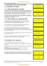
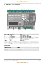
16. THE FIRE ALARM CONDITION 


16.1 Viewing a fire alarm event 

 
The way the ID2 panel shows fire alarm information has been changed slightly from previous versions of the 
panel. The LCD screen text has been altered to show the first & last zone entering the alarm condition. 
 
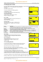
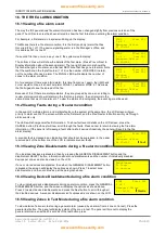
For Example, a first alarm on a system will bring up the display: 
 
This Means there is a fire alarm condition. It is the first (and only) alarm that has  
Occurred (Fire 1 of 1) The device signalling alarm is in the Manager`s office, and 
It is address 001 in zone 01. 
 
If a second fire then occurs in say zone 2, the system would display: 
 
The bottom 2 lines will still show the details of the first alarm (Press Prev or Next to  
Display information about the second alarm). The top right hand corner shows the  
first zone that gone into alarm, and the last NEW zone that has gone into alarm. Note  
that the numbers in the top left corner (1 of 2) is the number of DEVICES in alarm,  
not the number of zones in alarm. The ZONAL LEDS will indicate the number of  
zones in the alarm condition. 
 
So for example, if there was a third alarm, this time from zone 1 again, the right hand  
corner would continue to show First alarm ZONE 1, Last alarm ZONE 2. This allows  
the fire brigade to see the spread of the fire. 
 
Because of this, if there are multiple alarms, they are grouped by zone, so scrolling to  
review alarms would show all alarms in the first zone in alarm , then all alarms in the  
second zone that went into alarm etc. To view the alarms chronologically, the event log must be used. 
 

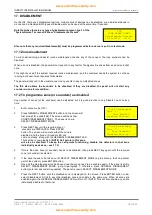
16.2 Viewing Faults during a fire alarm condition 

 
In the event of multiple alarms, and multiple faults on the system at the same time, the LCD screen will give 
priority to alarm events. The screen will show the first alarm, and the Prev/Next scroll buttons will cycle through 
alarm events only. 
 
The LEDs will show general fault information.  To show fault event details on the LCD screen, press the 
CANCEL button. Prev& next will now scroll through the faults. Press cancel to return to viewing the fire alarm 
information. (If the panel is left viewing a fault, after a short period of inactivity, the panel will revert to the fire 
alarm display) 
 
A sounder fault is classed as an Indication that should not be supressed, to the panel  
reserved part of the bottom line of the LCD to indicate sounder faults.  


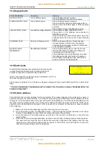
16.3 Viewing Zone Disablements during a fire alarm condition 


If no individual devices are disabled, then by pressing the GENERAL DISABLEMENT button and the 
disablement SELECT button, information about zone disablements and the number of individually disabled 
devices per zone can also be viewed on the LCD. 
 
If one or more devices are disabled, then when the GENERAL DISABLEMENT button  
is pressed, the screen will display the options as shown. Press 1 to select zone  
disablements, and then continue as per the paragraph above. 
 

16.4 Viewing Device Disablements during a fire alarm condition 


To view individual device disablements during an alarm condition, press the GENERAL  
DISABLEMENTS button, and the screen will display the options as shown above.  
Press 2 to select device disablements, and press the Next button to scroll through all  
the disabled devices. A sounder disablement isn’t supressed, so is shown on the LCD. 
 

16.5 Viewing Zones in Test Mode during a fire alarm condition 


To view details of a zone in test during a general alarm (caused by an alarm from a zone not in test), Press the 
general test button. The panel will display details of the zone in test. The panel will time out to display the 
general alarm screen within 20 seconds of the last button press. 

FIRE       First Z01 
1 of 1 
Managers Office 

Z1 ID:001 

FIRE       First Z01 
1 of 2      Last Z02 
Managers Office 
Z1 ID:001 

FIRE       First Z01 
2 of 2      Last Z02 
Kitchen 

Z2 ID:017 

FIRE       First Z01 
1 of 3      Last Z02 
Managers Office 

Z1 ID:001 

Disablement 
1: Zones 

2: Devices 

FIRE       First Z01 
1 of 1 
Managers Office 
Z1 ID:001      

 Fault


FIRE       First Z01 
1 of 1 
Managers Office 
Z1 ID:001    

 Disable


www.acornfiresecurity.com

www.acornfiresecurity.com

Summary of Contents for ID2/4

Page 1: ...ware Versions PANEL 1 N LOOP O N Approved Document No GLT 211 7 1 Issue 1 9 Author MG NJ Date 06 04 2016 INTELLIGENT 2 WIRE FIRE DETECTION SYSTEM WITH ID TECHNOLOGY INSTALLATION MANUAL www acornfirese...

Page 2: ...7 ZONE WIRING 12 7 1 Specific device wiring instructions 13 7 1 1 CP3 AD Manual Call Point 13 13 7 1 2 MKII detectors All types Base connection 13 7 1 3 ZAI MI Input Module 14 7 1 4 ZAIO MI Input out...

Page 3: ...3 16 2 Viewing Faults during a fire alarm condition 33 16 3 Viewing Zone Disablements during a fire alarm condition 33 16 4 Viewing Device Disablements during a fire alarm condition 33 16 5 Viewing Zo...

Page 4: ...th point eg building plumbing will help to discharge any static Always hold the PCB by its sides and avoid touching the legs of any components Keep the PCB away from damp dirty areas e g in a small ca...

Page 5: ...10 Test Condition Option with requirements The ID2 also has the following ancillary functions not required by the Standard Serial repeater output RS485 2 2 Power Supply Section The ID2 Fire Alarm Pan...

Page 6: ...ed sounders but also has 2 conventional sounder circuits All sounders on a ID2 panel will activate on any alarm It has been designed to give the advantages of an addressable system with the simplicity...

Page 7: ...step manner the procedure for the basic design and installation of the ID2 range of Fire Alarm Control Panels It gives detailed instructions on how to use all the features on this fire alarm panel For...

Page 8: ...s a bit of thought to zone allocation during the system design stage 1 Decide on the zone allocation for the system Each default zone can have a maximum of 15 devices fitted Consider the simplified 3...

Page 9: ...g to BS5839 Pt1 2013 Clause 26 Fire Detection and Alarm Systems for Buildings Code of Practice for System Design Installation and Servicing are Standard fire resisting cable to PH30 classification of...

Page 10: ...e that holds the panel manuals If semi flushing or fitting to a tight space remember to remove the manuals before fitting to the wall Fix the enclosure to the wall using the three mounting holes provi...

Page 11: ...el via the cable gland the mains cable should be passed twice through the provided ferrite This is made easier by removing the outer insulation The cable is then connected to the Live Earth and Neutra...

Page 12: ...CALCULATIONS The two batteries are wired in series to give 24 Volts Connect the ve of Battery 1 to the black battery charger lead Connect the ve of Battery 2 to the red battery charger lead The ve of...

Page 13: ...be wired with up to 8 separate radial circuits each with 15 devices per circuit It may also be wired as a single loop When Wired as a Loop Zone 1 is used as Loop OUT Side A and Zone 2 is used as Loop...

Page 14: ...negative out terminal on the call point The following terminals are used for connecting the call point 2 x Negative in terminals note if you only connect to the negative in terminals then the isolator...

Page 15: ...Date 06 04 2016 PAGE 14 Deep Base MKII CB D Common Base MKII CB 7 1 3 ZAI MI Input Module The end of line resistor value is 20K and the trigger resistor value is 1 K 7 1 4 ZAIO MI Input output Module...

Page 16: ...der circuit is 10K When using the ZASC make sure the PSU being used has a fault output relay so that in the event of a power supply fault it is reported to the control panel Note All Power Supplies us...

Page 17: ...It may also be programmed via the handheld programming tool Connecting the sounder is done using the terminals in the back box of the device Please refer to the above diagram 7 1 8 Sandwich Sounder T...

Page 18: ...C Wall Mount MKII ARL W There are two versions of the remote LED Wall mounted and Ceiling mounted The ceiling mounted version requires a standard detector base Each version of the remote LED can moni...

Page 19: ...el translates the address into a zone and ID Each zone starts with ID1 in order to simplify the addressing To assist with setting the dip switches there is a free app available for download on the APP...

Page 20: ...OFF OFF OFF ON OFF ON 2 14 ON OFF OFF OFF OFF ON ON ON 6 14 ON OFF OFF OFF OFF ON OFF ON 2 15 OFF OFF OFF OFF OFF ON ON ON 6 15 OFF OFF OFF OFF OFF ON OFF ON 3 1 OFF ON ON ON ON OFF ON ON 7 1 OFF ON...

Page 21: ...least 5V of superimposed data signal The exact calculation equations are beyond the scope of this manual because of the distributed load of the sounders on the loop but the following table gives a rou...

Page 22: ...O relays to the detector circuits Fault Output FAULT This is a SELV volt free relay that operates in the Fault condition It is Normally Energised which ensures it can give a fault signal even in the e...

Page 23: ...ing the wiring Figure 6 Cable connections All cables entering the enclosure should have cable glands which will prevent unwanted openings in the enclosure The Zone circuits should be connected to the...

Page 24: ...2 repeaters can be powered from the Aux24V DC output on the panel If 3 or more are to be connected then they must be powered from external 24V power supplies The panel supports up to 8 repeaters ID2...

Page 25: ...ws that pressing NEXT button will take you to Engineer Menu 2 4 Press button 1 will bring up the Zone menu Press 1 to view zone contents or press 2 to reconfigure the zones 5 Press 2 to reconfigure th...

Page 26: ...d Select option 1 to set time date Enter the Day Month Year Hour Minutes as prompted and press enter to save or Cancel at any time to exit 12 6 Changing the alarm Tones sounders For most applications...

Page 27: ...signals a MCP alarm when operated Used when device being monitored is Manually triggered and the system is set to distinguish manual automatic alarms P PREALARM I O signals a Pre Alarm when operated...

Page 28: ...ges The panel will have one of 2 language banks English Spanish Portuguese French Italian OR English Hungarian Serbian Lithuanian Other languages are available on request 12 10 Software Versions From...

Page 29: ...w Confirming alarm 3 If the device in alarm has zonal verification set the panel will turn on the sounders of all other detectors set to zonal verification in that zone 4 If the detector drops below t...

Page 30: ...set This brings up the screen to select to reset The panel can be reset as follows Option Item Function 1 Logs Clears event log Note that the Event counter is not reset Code 159 to reset 2 Factory Set...

Page 31: ...n alarm LED Flasher Press 4 Ring sounder Press GENERAL TEST Select alarm verification Press 8 Configure Sandwich Sounder Base Press 7 Disable this device Press General Disable Configure I O OUTPUT Pre...

Page 32: ...This device is signalling an internal fault by returning a value of less than 8 Device Label This is the 20 character description of the device location entered by the installer To change this Press E...

Page 33: ...recorded are Power On Startup Panel Reset Evacuate Access Level 2 Access Level 1 Sounders Silenced Configure Loops Time Date Set Zone Disabled Zone Enabled Device Disabled Device Enabled Zone Test St...

Page 34: ...e LEDs will show general fault information To show fault event details on the LCD screen press the CANCEL button Prev next will now scroll through the faults Press cancel to return to viewing the fire...

Page 35: ...he screen will first prompt for a code 248 The screen will then show ZONE DISABLEMENT ZONE 1 The panel is now in SELECT DISABLEMENT MODE 3 Press NEXT key until the required zone or sounders are DISPLA...

Page 36: ...ED ZONES To view which zones are disabled press 1 and then scroll through all the zones by pressing the Next button If a zone is not disabled the screen will show If a zone is disabled the screen will...

Page 37: ...d Zone Test LEDs will now be lit 7 Detectors in this zone can now be tested with smoke spray The Detector will light it s LED until the smoke clears then it will reset The Sounders the fire relay are...

Page 38: ...lier If the wiring polarity is correct check that there is no cable break on the loop If there is a break the panel will report the break after 60 seconds or so and the break can be verified my measur...

Page 39: ...ine the problem line Note connecting other equipment eg an oscilloscope or a PC to the panel can give an earth fault The Screen will indicate if it is a Positive or Negative voltage shorting to earth...

Page 40: ...unning condition due to various unexpected phenomena This will result in the panel attempting to correct itself Should this fault occur the System Fault LED General Fault LED General Fault relay and f...

Page 41: ...es 20 2 Device Values for Battery calculation Device Quiescent Alarm Comment ID2 Panel 50mA 102mA This is the current used during mains failure ID2 Repeater 50mA 75mA Fyreye MKII Addressable Optical S...

Page 42: ...r panel IQD 4 x 10x0 9 0 6 0 65 1 0 1000 4 x 11 25 1000 0 045 A IAP 0 102A IAD 4 x 10x7 2 2 5 7 3 2 0 1000 4 x 83 8 1000 0 3352 A Therefore using the equation Battery Size Standby time in Amp Hours 1...

Page 43: ...al sounders 11 Fault Relay Volt free relay normally energised Operates on any fault 12 Fire Relay Volt free relay Operates on a fire condition 13 RS485 Connection for Repeater panel 14 15 RS232 NOT AC...

Page 44: ...AT C I E OUTPUT 900 mA IMIN AT C I E OUTPUT 0 4 mA OUTPUT VOLTAGE RIPPLE 700mV MAX CURRENT DRAW BY PSE 2mA MAX BATTERY INTERNAL RESISTANCE RIMAX 1 5 CHARGER VOLTAGE 27 6V 22 24 o C CHARGER CURRENT 300...

Page 45: ...rences to 2013 version 4 occurrences Added loop wiring terminal information Added info to Electrical Spec Max sounders Max loop zone current Aux 28V voltage current Changed number of repeaters that ca...

Reviews: