MKII-Axx Installation Guide
32-0068-r03
1 / 3
17/10/2017
Zeta Alarms Limited, 72/78 Morfa Road, Swansea, SA1 2EN
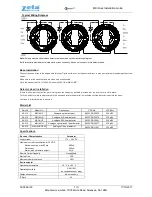
Typical Wiring Diagram
Note:
Polarity must be observed on detector as indicated on schematic wiring diagram.
Earth terminal is provided to maintain earth screen continuity. It does not connect to this detector head.
Base Installation
Connect the zone wires to the appropriate terminal. Tighten with a correct sized screwdriver: a wrong screwdriver may damage the screw
heads.
Make sure that the base contacts are clean and unobstructed.
Note, the base model No. for MKII-A Series is MKII-CB or MKII-CB/D.
Detector Head Installation
If there is still minor construction work in progress, the head may be fitted, provided that the dust cover is still in place.
To fit the detector, mate the detector onto the base and rotate the detector in clockwise until the detector loads into the base.
Continue to twist clockwise to secure it.
Model List
Specifications
Electrical Characteristics
Parameter
Loop voltage
17 V
– 28 V DC
Maximum current consumption, at 24 VDC
Switch-on surge, max 65 ms
Quiescent
Alarm (with no remote output.)
800uA
500uA
5mA
Remote Output Capacity
Vloop@5mA
Startup Time
15S
Maximum cable resistance
50Ω
Environmental
Operating temperature
-10 °C to + 80 °C
Operating humidity
0-95% RH
(no condensation or icing)
Design environment
Indoor use only
IP Rate
42
Part No
Model No.
Description
CPR No.
LPCB No
80-210
MKII-AOP
Analogue optical detector
0832-CPR-F0075
330n/02
80-212
MKII-AHR
Analogue A1R heat detector
0832-CPR-F0079
330q/04
80-214
MKII-AHF
Analogue A2S heat detector
0832-CPR-F0081
330q/03
80-216
MKII-AOH
Analogue optical and A1 heat detector
0832-CPR-F0077
330p/02
80-218
MKII-AHF/CS90
Analogue CS heat detector
0832-CPR-F1921
330q/05


