background image

REF #0907-53

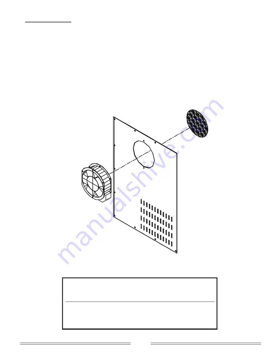
COOLING FAN:

A cooling fan is installed on the left side, at the back of the unit.  The function of this fan is to maintain the ambient
temperature surrounding the motors at the proper level as recommended in the standard.  It is imperative that the
wire netting be kept clean and free of obstructions as this could cause the fan to stop which would result in serious
damages to the air circulating motor inside the oven and would void the warranty of this product.


20

WARNING

INTAKE


FANS


AND


SLOTS


ON


REAR


PANELS


MUST


BE


CLEANED


WEEKLY

.


ANY


OBSTRUCTIONS


WILL


CAUSE


MOTORS


TO


SEIZE

.

AVERTISSEMENT

LES


PRISES


D

AIR


ET


LES


OUVERTURES


DANS


LES


PANNEAUX


ARRIÈRES


DOIVENT


ÊTRE

NETTOYÉS


À


TOUTES


LES


SEMAINES

.


TOUT


BLOCAGE


DE


CES


OUVERTURES


PEUT


FAIRE


SAISIR


LES


MOTEURS

.

Summary of Contents for CE 2416

Page 1: ...ACTURING INC MANUFACTURIER D EQUIPEMENT EN ALIMENTATION INC 6450 HUTCHISON MONTREAL QUEBEC H2V 4C8 TEL 514 278 4621 FAX 514 278 4622 e mail info zesto ca www zesto ca S N E V O R O Y E V N O C C I R T C E L E 8 1 4 2 6 1 4 2 E C X L E D O M D H 8 1 0 3 8 1 0 3 E C X 8 1 0 4 E C X 2 3 6 3 4 2 6 3 E C X 2 3 8 4 4 2 8 4 E C X 2 3 0 6 4 2 0 6 E C X ...

Page 2: ...POWER 2 CAUTION Electical disconect breaker should be installed on each oven section with a minimum 3mm spaced contact Disconect the power supply before any repairs or maintainance work is perfomed on oven CAUTION Risk of electric shock Do Not Obstruct Access to this Panelboard No Storage in this Area NOTICE A permanently connected appliance provided with casters or wheels on all legs of the appli...

Page 3: ...t n o C d e e p S 8 E C N A N E T N I A M 1 1 9 g n i n a e l C 0 1 9 g n i n a e l c r o f l a v o m e r t l e B 1 1 E L P U O C O M R E H T R I A S T N E M T S U J D A 5 1 2 1 n o i t u b i r t s i D r i A f o t n e m t s u j d A 5 1 2 1 e l p u o c o m r e h T 5 1 E C I V R E S L A C I N H C E T 0 2 6 1 m e t s y s g n i t a e h l a c i r t c e l E 7 1 6 1 r o t o M r a e G 8 1 r o t o M r e w ...

Page 4: ...ts voltage phasing Remove back panel and pass the service line through the rear of the unit and connect to the teminal block WARNING ADEQUATE MEANS MUST BE PROVIDED TO LIMIT THE MOVEMENT OF CASTERED APPLIANCES A RESTRAINING DEVICE IS REQUIRED FOR ALL TYPES OF MOVEABLE APPLIANCES WARNING INSTALLATION AND REPAIR SHOULD BE DONE BY A QUALIFIED SERVICE PERSON THE APPLIANCE SHOULD BE INSPECTED BEFORE US...

Page 5: ...tional Sanitation Foundation NSF In Canada the installation must conform with local codes or in the absence of local codes with the current CAN CGA B149 Installation Code The oven when installed must be electrically grounded in accordance with the local codes or in the absence of local codes with the current Canadian Electrical Code CSA C22 2 Number 109 In the United States installations must conf...

Page 6: ...REF 0907 53 6 MODELLE CG CE 3018 3018HD 4018 MODELLE CG CE 3624 3632 4824 4832 6024 6032 1 2 3 4 5 6 7 8 9 10 ...

Page 7: ...the program 2 Press till appears press or till you find 0 0 3 Press till appears press or till you find 2 4 Press till appears press or till you find 0 5 Press and hold for 5 seconds till appears then keep pressing togling till appears press or till you find K thermocouple 6 Press till appears press or till you find Fº or Cº 7 Press till appears press or till you find 0000 8 Press till appears pre...

Page 8: ... IF DIRECTION IS CHANGED BE SURE THAT BELT LINKS ARE CHANGED LINKS SHOULD ALWAYS BE IN PULLING DIRECTION see page 12 CAUTION In case of breakage of the electronic board do not touch any component do not attempt to repair it Service and calibration of the electronic board require special instruments and must be performed by the factory only Failure to do so would void the warranty and the replaceme...

Page 9: ... chain cover panel STEP 3 Lift belt and move forward thus loosening chain from belt shaft sprocket STEP 4 Now you can remove the belt by carefully pulling back towards you STEP 5 Remove bottom crumb tray first then bottom air distribution panel and then the top air distribution panel Cavity is now empty To clean interior of oven cavity wash with soap and water If residue is hard or difficult to cl...

Page 10: ...roduct CLEAN WEEKLY THIS SHOULD BE DONE BY PASSING A DAMP CLOTH OVER WIRE NETTING ATTENTION Never use pressure water hose Jet Spay to clean oven to prevent any electrical hazards REMOVING AND CLEANING WIRE BELT FRAME STEP 1 Rotate belt until you find chain link fasteners STEP 2 Undo chain link fasteners STEP 3 Roll belt and clean Now you may clean stainless steel frame with soap and water if resid...

Page 11: ...e movement of the splicing strand between steps When bending the splicing strand try to limit bending to straight por tions of the strand rather than in the Z bend area Splice one side completely before starting the other side After completely splicing the belt it is advisable to go along the width of the belt straightening the spliced in strand NOTE DEPENDING ON WIDTH OF BELT THERE MIGHT BE ONE T...

Page 12: ... E C 3 8 1 0 3 E C 3 8 1 0 4 E C 4 4 2 6 3 2 3 6 3 E C 4 4 2 8 4 2 3 8 4 E C 5 4 2 0 6 2 3 0 6 E C 6 D D 2 3 0 4 E C 4 D D 2 3 5 6 E C 6 ADJUSTABLE AIR DISTRIBUTION PANELS Ovens have a top adjustable air distribution panel bottom adjustable air distribution panel and crumb tray Top adjustable air distribution panel Bottom adjustable air distribution panel Crumb tray 1 Lift and pull out front panel...

Page 13: ...hing top large lever twords the back of the conduit decreases the quantity of air on top To shift air in top conduits 2 Loosen bolts on top of conduits Pushing top small lever twords the front of the conduit shifts the air to the front Pushing top smal lever twords the back of the conduit shifts the air to the back Bottom Air Distribution panel has one adjustment in each conduit to control the dis...

Page 14: ...REF 0907 53 14 ...

Page 15: ... to give more or less heat in the combustion chamber 15 W E I V P O T W E I V T N O R F L E D O M A S N O I S N E M I D B S N O I S N E M I D C S N O I S N E M I D 8 1 4 2 6 1 4 2 m m 7 5 4 1 2 m m 0 8 1 6 1 1 7 m m 3 1 2 1 8 1 0 3 m m 7 5 4 1 2 m m 5 4 2 8 5 9 m m 3 1 2 1 8 1 0 4 m m 7 5 4 1 2 m m 3 7 2 4 3 0 1 m m 3 1 2 1 4 2 6 3 2 3 6 3 m m 5 4 4 3 1 m m 7 0 4 6 1 m m 0 3 6 1 3 1 4 2 8 4 2 3 8 ...

Page 16: ...ents follow the steps below STEP 1 Disconnect from power source Remove side panel carefullyby first removing screws holding temperature and speed control and then remaining screws STEP 2 Remove wires components and screws holding hinged panel L E D O M S L I O C D E S O L C Y T I T N A U Q 8 1 4 2 6 1 4 2 E C 3 8 1 0 4 8 1 0 3 E C 3 2 3 6 3 4 2 6 3 E C 6 2 3 8 4 4 2 8 4 E C 9 2 3 0 6 4 2 0 6 E C 9...

Page 17: ...n the heating elements in the oven if the interior heat rises above the permitted level This control card also verifies at the beginning of the cycle that all the components are properly functioning Any failure the system shuts down a red light appears on the front panel and must them be reset Reset by depressing the reset button in front panel When the oven is shut off the TIME DELAY option start...

Page 18: ...REF 0907 53 GEAR MOTOR 18 2416 2418 3018 4018 3624 3632 4824 4832 6024 6032 4032DD 653DD ...

Page 19: ...g the blower assembly 6 Press down on the back of the motor to disengage the bracket from the slot and pull out the blower assembly towards you 7 Start the motor to verify the blower balance make sure nothing will come in contact with the blower cage If the blower cage is defective remove it taking care to verify the exact position of the hub on the motor shaft in order to install correctly the ne...

Page 20: ... and free of obstructions as this could cause the fan to stop which would result in serious damages to the air circulating motor inside the oven and would void the warranty of this product 20 WARNING INTAKE FANS AND SLOTS ON REAR PANELS MUST BE CLEANED WEEKLY ANY OBSTRUCTIONS WILL CAUSE MOTORS TO SEIZE AVERTISSEMENT LES PRISES D AIR ET LES OUVERTURES DANS LES PANNEAUX ARRIÈRES DOIVENT ÊTRE NETTOYÉ...

Page 21: ...REF 0907 53 21a ...

Page 22: ...REF 0907 53 21b ...

Page 23: ...REF 0907 53 22a ...

Page 24: ...REF 0907 53 22b ...

Page 25: ...n i a h C n i a h c e h t f o n o i s n e t t s u j d A n e v e t o n s i g n i k o o C e h t f o t n e m t s u j d a r e p o r p m I s r e g n i f l a u n a m e h t n i s n o i t c u r t s n i e e S s i e r e h t d n a g n i t a r e p o s i n e v O t a e h o n n o f i t h g i l h c t i w s t i m i l i h k c e h C l e n a p l o r t n o c n i t h g i l d e r s e o d t i f I n o t t u b t e s e r h ...

Page 26: ...k a b r a p S T N A S S I O R C n i m 5 4 o t 4 9 9 1 0 9 3 h s e r f S T N A S S I O R C n i m 0 1 o t 9 9 9 1 0 9 3 h s e r f S N I F F U M n i m 3 1 o t 2 1 9 9 1 0 9 3 h s e r f S E I K O O C S T I U C S I B n i m 5 6 o t 5 4 9 9 1 0 9 3 T A E M Y R T L U O P d e k o o c e r p S G N I W N E K C I H C n i m 5 6 o t 5 5 5 6 2 0 1 5 h s e r f S G N I W N E K C I H C n i m 0 2 o t 8 1 9 9 1 0 9 3 ...

Page 27: ...MENT PARTS AT NO CHARGE AND WILL ALSO PAY FOR REASONABLE LABOUR COSTS FOR REPAIR WORK EXCEPT FOR REFRIGERATION 90 DAYS LABOUR ONLY DURING REGULAR WORKING HOURS ALL WARRANTY REPAIRS MUST BE APPROVED BY AN AUTHORIZED COMPANY OFFICIAL BEFORE ANY WORK IS DONE LABOUR COSTS TO BE BORNE BY ZESTO MUST NOT EXCEED THE RETAIL PRICE OF THE PARTS REPLACED ALL REQUESTS FOR RE IMBURSEMENT OF CHARGES MUST BE ACCO...

Reviews: