


Installation & Operation • 11
INSTALLATION & OpERATION
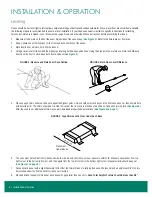
Kickplates
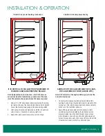
Each case is shipped with a front kickplate. Cases with end panels are shipped with 1 side kickplate per end panel. Cases that join together are
shipped with a kickplate splice.
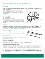
Front and side kickplates are attached to the case bases using Tinnerman
clips. Position the front kickplate so the flange is on top and facing outward.
The screw (supplied) goes through the kickplate and into the Tinnerman clip
(
1. Install Tinnerman clips at each base.
2. Install side kickplate.
3. Install front kickplate.
4. Insert fasteners to secure kickplates.
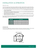
There is a natural gap between the top of the kickplate and the underside of
the Reveal Merchandiser
®
that allows airflow of 20 CFM/foot. If more airflow is
required, contact the factory to order optional louvered kickplates (provides 60
CFM/foot).
Bumper
Cases are supplied with a protective bumper shipped loose on top of each case. The steel bumper support and snap track are factory-installed
on the front of the case. The bumper may need trimming before snapping it onto the snap track. Door leveling must be completed before
attaching the bumper (
See "Door Leveling (Door Sag/Sawtooth)" on page 10
).
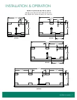
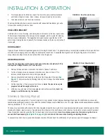
Top Trim Splice
Top trim is factory installed, and it hides the door hardware located on the top
exterior of the case. Joint splices are shipped loose and must be field-installed at
the upper case joints (
). Screw the top trim joint splice to the top trim.
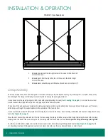
CoolView
®
Doors
Door leveling must be completed before attaching the bumper (
(Door Sag/Sawtooth)" on page 10
COOLARC
™
DOOR HANDLES
The Coolarc
™
door handle is attached to the glass surface of the door by an industrial-grade adhesive.
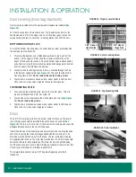
DOOR CLOSER / ADJUSTING DOOR TENSION
The door closer is a spring cartridge that automatically closes the door. It is located on the bottom of the hinge-side of the door. a square pin
inside the door closer fits into a square opening on the door, transferring the spring tension to the door. This means that the square pin must be
aligned with the square opening when installing a door. an adjustment screw on the front can be used to increase or decrease tension.
1. Open the door to observe current door tension. a properly tensioned door will close itself gently and not swing open.
2.
Use a flathead screwdriver to turn the door tension screw (
). Do not use power tools; a screwdriver allows
for more control.
FIGURE 14: Kickplate Installation
DETAIL A (ASSEMBLED)
4. INSERT FASTENERS TO SECURE KICKPLATES
3. INSTALL KICKPLATE FRONT
1. INSTALL TINNERMAN NUTS AT EACH BASE
2. INSTALL KICKPLATE END
DETAIL A (EXPLODED)
BASE
TINNERMAN NUT
KICKPLATE END
KICKPLATE INSTALLATION
KICKPLATE FRONT
REV.
SP-6108
B
SPECIFIED, ALL DIMENSIONS
(PER SP-0457)
REVEAL
TOLERANCES:
RELEASED
PART WEIGHT:
(IN LBS)
REVISION INFORMATION
B REMOVE EXTRA KICKPLATE COMPONENT FROM DETAIL A.
978
NO MANUAL REVISIONS
CONSENT OF ZERO ZONE, INC. IS STRICTLY PROHIBITED.
CAD DRAWING
REPRODUCTION OR OTHER MEANS, WITHOUT THE WRITTEN
FINISH:
(PER SP-0404)
(UNLESS OTHERWISE SPECIFIED)
(PER SP-0154)
MATERIAL:
SIZE
NOT TO SCALE
Ron Oman
SCALE:
MODELED BY:
A
ZERO ZONE, INC.
DOCUMENT OR DISCLOSURE OF ITS CONTENTS; BY
ARE IN DECIMAL INCH
7/27/2016
B
1 OF 1
SP-6108
KICKPLATE ASSEMBLE FIELD
SHEET:
DATE:
REVISION
SHEET
DRAWN BY:
UNLESS OTHERWISE
USA 53153
DRAWING No:
DESCRIPTION:
BY
DATE
ECN No.
REVISION DESCRIPTION
No.
BF
6/9/2020
COPYRIGHT INFORMATION
THIS DRAWING AND THE INFORMATION CONTAINED WITHIN, IS
THE SOLE PROPERTY OF ZERO ZONE, INC. ANY USE OF THIS
110 NORTH OAKRIDGE DRIVE
NORTH PRAIRIE, WISCONSIN
David Giese
A
Base
Front
Kickplate
Side Kickplate
Tinnerman Clip
Fastener
F
5.75
GRAIN DIRECTION
IF STAINLESS STEEL
.88
.88
FINISH SIDE REF
NOTE 1
.41
.63
4.50±.03
.188±.010
NOTES:
1. NOTED FACE AND ALL ADJACENT EDGES ARE TO BE FINISHED
PART INFORMATION
PART NUMBER
BASE METAL
FINISH
37-0437-P1
.032 ALUMINUM
BLACK
37-0437-P2
.032 ALUMINUM
WHITE COIL COAT
37-0437-P3
.032 ALUMINUM
PEARL COIL COAT
37-0437-P4
.032 ALUMINUM
SAVANNAH YELLOW COIL COAT
37-0437-P5
24 GA GALV
CHEM TREAT DRY
37-0437-P7
20 GA 204 STAINLESS STEEL
#4 BRUSHED
37-0437-P11
24 GA GALV
ANTIQUE COPPER TIGER DRYLAC
49/90620
37-0437-P16
24 GA GALV
TEXTURED WHITE
37-0437-P18
24 GA GALV
SILVER METALLIC
37-0437-P19
24 GA G60 GALV SEVILLE EMBOSSED EMBOSSED WHITE
37-0437-P20
24 GA GALV
MATTE BLACK TIGER DRYLAC
009/80450
37-0437-P21
24 GA GALV
MEDIUM GRAY, TIGER DRY LAC
049/70785 IRON GLIMMER EFFECT
POWDER COATED
37-0437-P23
24 GA GALV
GOLDEN BROWN
37-0437-P24
24 GA GALV
SPANGLED SILVER, POWDER-COAT
37-0437-P32
24 GA GALV
TYGER DRYLAC 049/707/89 db FINE
TEXTURE GLIMMER
37-0437-P33
24 GA GALV
TYGER DRYLAC 09/60610 BEIGE
FULL HT GEN 2
ZERO ZONE WORKMANSHIP STANDARDS SHALL APPLY PER
ES-08-1007
ASME Y14.41-2012 & ASME Y14.5-2009 SHALL APPLY AS REQUIRED
ALL DIMENSIONS IN INCH UNLESS OTHERWISE SPECIFIED
RELEASED
SIGNIFICANT DIMENSIONS DENOTED BY X.XX
OR X.XXX AND MUST MEET Cpk ≥ 1.33.
CRITICAL DIMENSIONS DENOTED BY X.XX
OR X.XXX
AND MUST MEET Cpk ≥ 1.66.
CAD DRAWING
NO MANUAL REVISIONS
COPYRIGHT INFORMATION
THIS DRAWING AND THE INFORMATION CONTAINED WITHIN,
IS THE SOLE PROPERTY OF ZERO ZONE, INC. ANY USE OF
THIS DOCUMENT OR DISCLOSURE OF ITS CONTENTS; BY
REPRODUCTION OR OTHER MEANS, WITHOUT THE WRITTEN
CONSENT OF ZERO ZONE, INC. IS STRICTLY PROHIBITED.
SEE CHART
SEE CHART
FINISH:
(PER SP-0154)
MATERIAL:
(PER SP-0404)
NOT TO SCALE
SCALE:
MODELED BY:
DRAWN BY:
9/1/2015
F
1 OF 1
37-0437
SPLICE TOP TRIM CRSTL/CRSTL
SHEET:
DATE:
REVISION
ZERO ZONE, INC.
110 NORTH OAKRIDGE DRIVE
NORTH PRAIRIE, WISCONSIN
USA 53153
DRAWING No:
DESCRIPTION:
REVISION INFORMATION
F
ADDED P32 AND P33
12552
12/29/2017
DB
No. REVISION DESCRIPTION
ECN No.
DATE
BY
UPDATED DIMENSIONS WITH NEW TITLE BLOCK
Kurt Albrecht
SHEET SIZE
A
TOLERANCES SHALL APPLY
UNLESS OTHERWISE SPECIFIED
.X = ± .1 .XX = ± .02
.XXX = ± .005 ANGLES, ± 1º
FIGURE 15: Top Trim Splice