Installation & Operation • 5
INSTALLATION & OPERATION
2. Snap a chalk line at the locations for the front and back positions of the base rails.
3. Mark locations of all joints (front and back).
4.
Using a laser level or transit, find the highest point along both base rail position lines. Using the high point as a reference, mark the
difference directly on the floor to each joint (front and back).
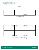
5. If you plan on using optional “hat channels” to raise the case height, place them under each pair of bases. On some cases, all bases are
not directly in line from front to back.
and
for base locations. The 3 and 4-door hat
channels will be angled slightly to support the front and rear bases because the bases themselves are not in line.
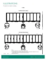
6. Place the required number of shims under each base or optional hat channel at each joint (front and back) to equal the highest point. The
case is designed with minimal gaps between adjacent doors to provide a clean appearance. To maintain even, consistent gaps and proper
door operation, the case must be leveled front-to-back and side-to-side. Check case squareness to within 1/8".
. Shims should not extend beyond the front case bases or they will interfere with the installation of kick plates. Tape all shims in place.
The shims should be oriented to sit under the front and rear bends of each base.
7. The RVLC30 2-door through 5-door cases have segmented bases mounted at the ends and under the center section of the case. The
RVLC30 1-door and RVLC30BB have full bases that run front-to-back and are located at the ends and under the center sections of the
case. Place additional support shims under all other bases or hat channels, leaving no gaps taller than one shim.
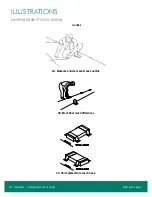
8. Tape all shims in place (
for the correct orientation of shims under the base or
channel.
9. If you are joining coolers to freezers, RVMC cases should be set with a slight backward tilt to offset the forward lean of a fully loaded case.
When joining a freezer and cooler in a short lineup, both cases should be tilted back with an additional 3/16" of shims under the front
bases after the case is leveled.
. On long lineups, the tilt back on the coolers should gradually increase while
working away from the cooler/freezer joint until the last case has an additional 3/8" of shims under the front base and the tilt back on the
freezers should gradually decrease to no additional shims while working away from the cooler/freezer joint.
.
10.
If you’ve purchased seismic restraints, specific instructions for attaching those restraints are included in your document package. These
instructions should be read and understood before the lineup is assembled.
Case Movement
!
CAUTION!
DO NOT PULL ON THE MULLIONS WHEN MOVING THE CASE. THE END FRAME CAN BE USED TO PUSH/PULL
THE CASE. DOLLIES MAY BE PLACED AGAINST THE CASE BOTTOM, BUT AVOID CRUSHING THE BUMPER
SUPPORT OR DRAIN PIPE.
WHEN USING A J-BAR, IT MUST NOT CONTACT THE SHEET METAL OF THE BUMPER SUPPORT, BUT SHOULD
CONTACT THE SHEET METAL OF THE BOTTOM FOAMED PANEL. THE BUMPER SUPPORT WILL BE DAMAGED
IF LIFTED BY A J-BAR. BE CAREFUL NOT TO PIERCE THE SHEET METAL WITH THE CORNER OF THE J-BAR.
The RVLC30 and RVLC30BB cases have steel protective support plates under the ends (not under insulated dividers). These are designed to
protect the end from Johnson Bar damage. Per NSF, these must be removed after cases are set.
The Back-to-Back cases are shipped with wood planks that allow the use of pipe rollers. These wood planks should be removed after the case
is moved to its final location (
).
MODEL
FORKLIFT
FROM ENDS
JOHNSON
BAR
FURNITURE
DOLLY
PIPE
ROLLERS
SAFE (CASE)
JACKS
RVLC30
X
X
X
X
RVLC30BB
X
X
X
X
X
Care should be taken when moving the cases. The doors should be secured so they cannot open while the case is moved.
Summary of Contents for CRYSTAL MERCHANDISER
Page 25: ...Illustrations Case Squareness 23 Illustrations Figure 6 Case Squareness Refer back to page 5...
Page 26: ...24 Illustrations Shim Placement Illustrations Figure 7 Shim Placement Refer back to page 5...
Page 27: ...Illustrations Shim Orientation 25 Illustrations Figure 8 Shim Orientation Refer back to page 5...
Page 29: ...Illustrations Spacer Block 27 Illustrations Figure 10 Spacer Block Refer back to page 6...
Page 34: ...32 Illustrations Drain Line Illustrations Figure 15 Drain Line Refer back to page 7...
Page 38: ...36 Illustrations Electrical Box Illustrations Figure 19 Electrical Box Refer back to page 11...


