Defrosting • 17
DEFROSTING
When the freezer first operates, the fans may cycle off and on a few times until coil temperature stabilizes below 10°F. The superheat must be
set for proper operation. Electric defrost models have a high limit thermostat installed on the coil, wired in series with the defrost heaters. This
thermostat opens if the temperature reaches 85°F.
.
Defrost Heater Element
.
The electric wire leads are connected in a raceway under the coil cover on the right-hand side of the case.
Heater Element Removal
The U-shape defrost heater has one leg located on the front of the coil and one leg located on the rear of the coil. The front heater is located
approximately 1" off the floor and the rear heater is approximately 2" off the floor. The heater is secured to the coil by a number of stainless steel
heater retaining clips. The heater is fastened to the floor on the right-hand side of the coil. Remove fasteners holding the heater to the floor.
The U-shape defrost heater can be removed by first pulling the front leg of the retaining clip away from the coil and sliding the heater out from
under the clip. The rear leg of the heater can then be removed by raising the retaining clips 2" at a time, working from right to left on the coil.
Repeat this process until the retaining clips are free of the coil. The heater will slide up with the retaining clip.
Heaters are installed in the reverse order of how they were removed.
Anti-Sweat Heaters
The case has one anti-sweat heater located in each mullion, including the end mullions, and one anti-sweat heater in the case sill. The mullion
heater is located behind the front metal strike plate. Remove the front fasteners on the mullion and remove the front strike plate to access the
heater. The case sill heater is located under the front metal strike plate below the door opening. Contact Zero Zone’s Service Department for
instructions for servicing this heater.
For locations with low humidity and tightly controlled ambient conditions the lower sill heater may be disconnected for additional energy savings.
Summary of Contents for CRYSTAL MERCHANDISER
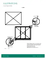
Page 25: ...Illustrations Case Squareness 23 Illustrations Figure 6 Case Squareness Refer back to page 5...
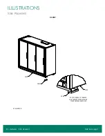
Page 26: ...24 Illustrations Shim Placement Illustrations Figure 7 Shim Placement Refer back to page 5...
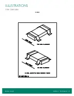
Page 27: ...Illustrations Shim Orientation 25 Illustrations Figure 8 Shim Orientation Refer back to page 5...
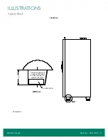
Page 29: ...Illustrations Spacer Block 27 Illustrations Figure 10 Spacer Block Refer back to page 6...
Page 34: ...32 Illustrations Drain Line Illustrations Figure 15 Drain Line Refer back to page 7...
Page 38: ...36 Illustrations Electrical Box Illustrations Figure 19 Electrical Box Refer back to page 11...


