background image


Installation, Service and User


INSTRUCTIONS 

FOR THE


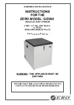
ZERO MODEL: GEV60


SINGLE LID CHEST FREEZER


3-WAY:  L.P. Gas, 230V Electric  

& 12V DC


ZERO APPLIANCES (PTY) LTD


Cat. I

3+ (28

–30/37) 

& I

3B/P (30)


WARNING: THIS APPLIANCE MUST BE 

EARTHED


ENSURE THAT THE GAS SUPPLY HOSE IS NOT IN 

CONTACT WITH OR NEAR THE BURNER BOX


Summary of Contents for GEV60

Page 1: ...THE ZERO MODEL GEV60 SINGLE LID CHEST FREEZER 3 WAY L P Gas 230V Electric 12V DC ZERO APPLIANCES PTY LTD Cat I3 28 30 37 I3B P 30 WARNING THIS APPLIANCE MUST BE EARTHED ENSURE THAT THE GAS SUPPLY HOSE...

Page 2: ...tor size 0 42mm diameter marked 13 Gas consumption 34 2 g h Electrical Supply 230V Mains Electricity 0 130W This appliance is a single lid single bin chest type freezer and has a hanging storage baske...

Page 3: ...ca may install a gas installation The installation must be installed in accordance with the requirements of SANS 10087 1 and any fire department regulations and or local bylaws applicable to the area...

Page 4: ...pe by briefly pressing on the safety valve knob A This will ensure that the flame lights quickly Do not press knob A for more than 15 seconds see Users note BURN BACK FIRE IN BURNER TUBE OR CHAMBER RE...

Page 5: ...ER BOX 1 Make sure that the electrical supply to the appliance is turned off 2 Open the shut off valve for the gas bottle or gas installation check that there is enough gas 3 Open flap B 4 Keep the fl...

Page 6: ...sperse and then repeat the ignition steps TO START 12V DC OPERATION 1 Make sure that the gas supply to the appliance is turned off 2 Make sure that the electric 230V supply to the appliance is turned...

Page 7: ...ll take about 1 hour after switching on IF THE APPLIANCE IS NOT COLD ENOUGH IT MAY BE BECAUSE 1 The ventilation of the absorption unit is inadequate Allow at least 100mm around Back sides and 600mm ab...

Page 8: ...rner and re tighten the nuts on the thermocouple Repeat the starting instructions and lighting procedure as laid out on page 4 USER OPERATING INSTRUCTIONS TO START GAS OPERATION 14 If the appliance is...

Page 9: ...oth and a small quantity of household detergent The lid seal should only be cleaned with soap and water and then thoroughly dried The absorption unit behind to the appliance should be cleaned with a b...

Page 10: ...Smell or deposits indicate a leaking unit see User instructions Check the functioning of the flame failure control adjust if necessary Check the functioning of the ignition device if fitted adjust if...

Page 11: ...areas GAS BURNER PARTS LIST 1 SANS BRASS HOSE TAIL 2 FLAME FAILURE DEVICE 3 M10 NUTS 4 M10 x 3 8 UNF JET HOLDER 5 M10 x 1 JET NUT 6 JET MARKED 13 7 MIXING TUBE 8 BURNER BOX 9 BURNER COVER 10 RETAINER...

Page 12: ...Made in South Africa Pty Ltd...

Reviews: