


48.
Leave the other links in their factory set
positions as shown on the cover.
6 Locate the four Main Board Power Supply
wires and unplug them from the Power
Supply. Plug this into the 4-way connector on
the DMX board.
7 Plug the 4 wire flying lead from the DMX board
into the Power Supply.
FOR SIRIUS 24 ONLY:
See Figure 1
Connect the 16-way ribbon cable from the DMX
board to the connector on the Right Hand Button
Board (EM5774; on the left as shown in Figure1).
Take care to insert the connectors the correct
way around.
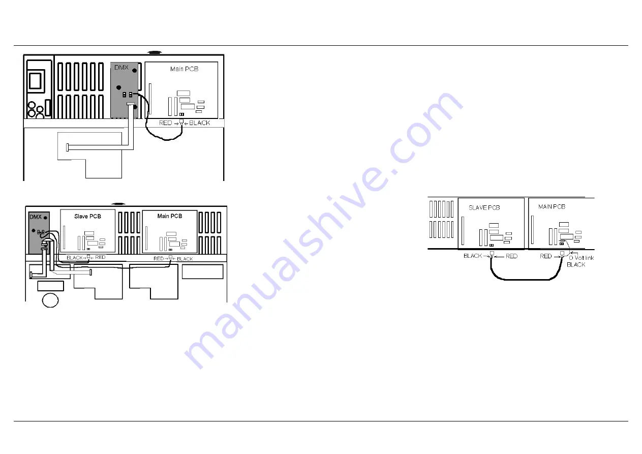
There are now two screen cables left coming
from under the DMX PCB.
Plug the connector of the longer cable into the 2
way connector now fitted to the main processor
PCB as shown here. Ensure that the colours are
fitted the correct way around as shown. The
spare cable should be coiled up and secured out
of the way.
FOR SIRIUS 48 ONLY:
See Figure 2
Locate the 16-way ribbon cable connecting the
Outer Right Hand Button Board (situated just
above the Power Supply) to the Inner Right Hand
Button Board (EM5774). Unplug this cable from
the Inner Right Hand Button Board and plug it
into the socket on the DMX board. Plug the flying
cable from the DMX board into the socket on the
Inner Right Hand Button Board. Take care to
insert the connectors the correct way round.
There are two screened cables coming from the
DMX PCB. Plug the longer cable into the 2 way
connector now fitted to the main processor PCB.
Plug the shorter cable into the similar 2 way
connector on the slave processor PCB. Ensure
that the colours are fitted the correct way around
as shown in Figure 2.
*
Note
DMX Card
The screened cables are attached to the DMX PCB with Molex
connectors the RED wire on these connectors need to be
nearest the Ribbon cables.
Removing DMX Card
Should the DMX card be removed, the Sirius 48
will only function as 24 channel desk unless the
two way connectors are linked with a screened
cable.Take the cable with two way connectors at
each end and fit as shown in Figure 3.
Note that the screen at one end of the cable is
soldered to the 0V point show in Figure 3.
Slaved desks
Where two Sirius desks (24 and/or 48) are being
used in a Master and Slave configuration, one
DMX Kit is needed for each desk,
Each desk then
gives its own DMX output. The two DMX
supplies then need to be connected
independently to its own Demultiplex unit
.
Fitting the Sirius DMX Kit
Fitting the Sirius DMX Kit
Page 3
Figure 2: Sirius 48
Figure 1: Sirius 24
Figure 3: Sirius 48 with No DMX


