

© Zennio Avance y Tecnología S.L.
Edition 5
Futher information
Page 2/2
SAFETY INSTRUCTIONS
•
Installation should only be performed by qualified professionals according to the laws and regulations applicable in each country.
•
Do not connect the mains voltage nor any other external voltage to any point of the KNX bus; it would represent a risk for th e entire
KNX system. The facility must have enough insulation between the mains (or auxiliary) voltage and the KNX bus or the wires of other
accessories, in case of being installed.
•
Once the device is installed (in the panel or box), it must not be accessible from outside.
•
Keep the device away from water and do not cover it with clothes, paper or any other material while in use.
•
The WEEE logo means that this device contains electronic parts and it must be properly disposed of by following the instructi ons at
http://zennio.com/weee-regulation.
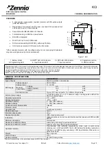
INPUTS SPECIFICATIONS AND CONNECTIONS
CONCEPT
DESCRIPTION
Number of S0 or dry
inputs
4
Inputs per common
2
Operation voltage
6VDC
Connection method
Screw terminal block
Cable cross-section
0.5-2.5mm² (IEC) / 26-12AWG (UL)
Maximum cable length
30m
Minimum pulse duration
30ms
WIRING DIAGRAMS
Figure 2: Example of connections with SO pulse generators
Attaching KCI to DIN rail:
Removing KCI from DIN rail:
BATTERIES REPLACEMENT
1.
Extract the battery holder from the upper side of KCI. It is recommended to have the bus KNX connected during this
process to prevent S0 pulses loss.
2.
Place the batteries in the battery holder (respecting the polarity shown) and insert it as indicated in the figure.
2
1
Figure 3: Mounting KCI on DIN rail