
© Zennio Avance y Tecnología S.L.
Edition 3
Page.
2
/
2
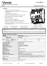
Attaching ZoningBOX 6 to DIN rail:
SAFETY INSTRUCTIONS
Installation should only be performed by qualified electricians following applicable regulations on preventing accidents, as
required by law
Do not connect Main Voltage (230VAC) or any other external voltages to any point of the BUS.
Connecting an external voltage might put the entire KNX system at risk.
This device contains a security short-circuit proof transformer.
Make sure during the installation that there is always sufficient insulation between the mains voltage 230VAC and the bus or
the extension inputs.
Once the device is installed, it must not be accessible from the outside.
Keep away from water and do not cover the device with clothes, paper or any other material when in use.
The WEEE logo means that this device contains electronic parts and it must be discarded properly following the instructions
of http://zennio.com/weee-regulation.
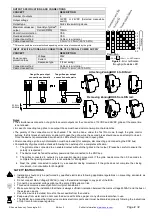
Two grilles per output
connection schematic
One grille per output
connection schematic
Removing ZoningBOX 6 from DIN rail:
OUTPUT SPECIFICATIONS AND CONNECTIONS
CONCEPT
DESCRIPTION
Number of outputs
6
Output voltage
12VDC or 24VDC (Selected meanwhile
switch)
Output type
Solid state switching device
Maximum values per
output
Quantity of grilles
(2)
2
Current (RMS)
750mA
Short-circuit protection
YES
Overload protection
YES
Connection method
Cable screw terminal
Cable cross-section
0.5mm² to 2.5mm² (26-12 AWG)
(2)
This value could be more restrictive depending on the current consumed by the grille.
INPUT SPECIFICATIONS AND CONNECTIONS OF EXTERNAL POWER SUPPLY
CONCEPT
DESCRIPTION
Power supply
protection fuse
Voltage
250V
Current
4A
Response type
F (Fast acting)
Connection method
Cable screw terminal
Cable cross-section
0.2mm² to 4mm² (26-10 AWG)
230V
AC
50/60Hz
Grille
Grille
Grille
Figure 2.
Error notification
through grille status LED
Notes
:
The simultaneous connection of a grille to several outputs nor the connection of 12VDC and 24VDC grilles at the same time
is not allowed.
In case of connecting two grilles to an output, those must have similar consumption characteristics.
The polarity of the connection must be checked. This can be done, under the Test On mode, through the grille control
buttons: the first press should imply an attempt to open the grille, while the second press should cause an attempt to close it.
Once the device is parameterized, switched-on LEDs should correspond to open grilles.
After connecting a grille, a synchronisation must be provoked (for example, disconnecting and connecting the KNX bus).
Compatibility of grilles must be checked following the next steps for a complete verification:
1. The grille must be connected to an enabled output, without other grilles in that output, (Please be careful to ensure the
polarity is respected).
2. The device must be fed with auxiliary power and then connected to the KNX bus.
3. The grilles connected to outputs try a sequential opening movement. If the grille needs more than 3.5 seconds to
complete the opening movement, it is not suitable for ZoningBOX.
4. Next, the grilles connected to outputs try a sequential closing movement. If the grille does not complete the closing
movement, it is not suitable for ZoningBOX.
Co
nn
ec
tio
n e
rro
r M
x
Ov
er
lo
ad
M
x
Po
we
r s
uppl
y f
ail
ur
e
L
x
L
x
L1 L2 L3 L4 L5 L6
0,5
1,0
1,5
2,0
2,5
3,0
3,5
Description:
LED On
LED Off
L
x
: Grille
x
LED
Ti
m
e (
s)
T
im
e (
s
)
Description:
L
x
: LED output
x
LED Off
LED On


