background image


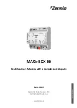
MAXinBOX 66


http://www.zennio.com


Technical Support:


http://support.zennio.com 


2


CONFIGURATION 

2.1


GENERAL 

After  importing  the  corresponding  database  in  ETS  and  adding  the  device  into  the 

topology  of  the  desired  project,  the  configuration  process  begins  by  right-clicking  into 

the device and selecting 

Edit parameters

ETS PARAMETERISATION 

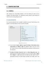
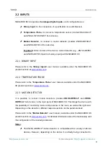
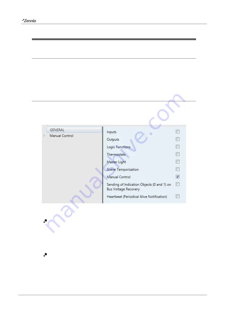
The only parameterisable screen available by default is General. From this screen it is 

possible to activate/deactivate all the required functionality. 


Figure 2. 

General screen


  Once activated,

 Inputs, Outputs,  Logical  Functions,  Thermostats, Scene 

Temporization

  and 

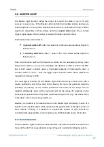
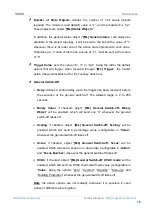
Master  Light

  bring  additional  tabs  to  the  menu  on  the 

left. These functions and their parameters will be explained in later sections of 

this document. 


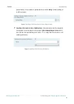
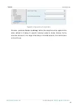
Sending  of  Indication  Objects  (0  and  1)  on  Bus  Voltage  Recovery

:  this 

parameter lets the integrator activate 

two new communication objects (“

Reset 

0

” and “

Reset 1

”), which will be sent to the KNX bus with values “0” and “1” 

respectively  whenever  the device begins operation (for  example,  after a bus 

Summary of Contents for MAXinBOX 66

Page 1: ...MAXinBOX 66 Multifunction Actuator with 6 Outputs and 6 Inputs USER MANUAL ZN1IO MB66 Application program version 1 4 User manual edition 1 4 _a www zennio com...

Page 2: ...Power Loss 6 2 Configuration 7 2 1 General 7 ETS Parameterisation 7 2 2 Inputs 9 2 2 1 Binary Input 9 2 2 2 Temperature Probe 9 2 2 3 Motion Detector 9 2 3 Outputs 11 2 3 1 Manual Control 11 ETS Para...

Page 3: ...mostat and master light modules 1 3 _a Changes in the application program Heartbeat functionality added Optimisation of the outputs inputs logic functions thermostat and master light modules New gener...

Page 4: ...of the above 6 multi purpose inputs configurable as Temperature probes Binary inputs i e pushbuttons switches sensors Motion detectors 10 customisable multi operation logic functions 4 independent the...

Page 5: ...e into the programming mode making the associated LED 5 light in red Note if this button is held while plugging the device into the KNX bus the device will enter into safe mode In such case the LED wi...

Page 6: ...ice the Test Prog LED will blink in blue colour for a few seconds before MAXinBOX 66 is ready External orders will not be executed during this time but afterwards Depending on the configuration some s...

Page 7: ...en it is possible to activate deactivate all the required functionality Figure 2 General screen Once activated Inputs Outputs Logical Functions Thermostats Scene Temporization and Master Light bring a...

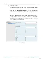
Page 8: ...econds Figure 3 Sending of Indication objects on bus voltage recovery Heartbeat Periodical Alive Notification this parameter lets the integrator incorporate a one bit object to the project Heartbeat O...

Page 9: ...at www zennio com 2 2 2 TEMPERATURE PROBE Please refer to the Temperature Probe user manual available under the MAXinBOX 66 product section at www zennio com 2 2 3 MOTION DETECTOR It is possible to c...

Page 10: ...ease refer specifically to the aforementioned user manual Motion detectors with references ZN1IO DETEC and ZN1IO DETEC N are not compatible with MAXinBOX 66 may report inaccurate measurements if conne...

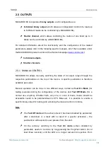
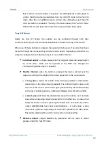
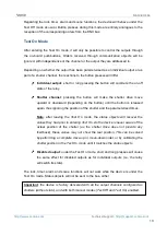
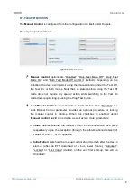
Page 11: ...e of its output relays through the respective pushbuttons on the top of the device A specific pushbutton is therefore available per output Manual operation can be done in two different ways named as T...

Page 12: ...long will make the output switch its on off state which will be reported to the KNX bus through the corresponding status object if enabled Shutter Channel when the button is pressed the device will a...

Page 13: ...ove upward or downward depending on the button until the button is released again thus ignoring the position of the shutter and the parameterised times Note after leaving the Test On mode the status o...

Page 14: ...on while switching to the Test On mode does require long pressing the Prog Test button Lock Manual Control unless the above parameter has been Disabled the Lock Manual Control parameter provides an op...

Page 15: ...ution of each function can depend on a configurable condition which will be evaluated every time the function is triggered through specific parameterisable communication objects The result after execu...

Page 16: ...four Zennio thermostats which can be enabled and configured independently Please refer to the specific Zennio Thermostat user manual available under the MAXinBOX 66 product section at the Zennio homep...

Page 17: ...ermostat setpoint or mode switch order a constant value a scene Only the trigger object and the twelve status objects are required to be binary on off The most typical scenario for this Master Light c...

Page 18: ...delay once the trigger has been received before the execution of the general switch off The allowed range is 0 to 255 seconds Binary Value if checked object ML General Switch off Binary Object will b...

Page 19: ...f the objects start with ML Courtesy Switch On On the other hand sending scene save orders is not possible for the courtesy switch on only orders to play scenes are allowed Note object ML Courtesy Swi...

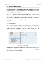
Page 20: ...r that output channel such temporisation will be interrupted and only the delay and the action of the new scene will be executed ETS PARAMETERISATION Prior to setting the scene temporisation it is nec...

Page 21: ...ring Scene Temporisations Therefore parameter Scene m Z Delay defines the delay that will be applied to the action defined in Z being Z a specific individual output or shutter channel for the executio...

Page 22: ...47 48 49 50 51 52 1 Byte I C W DPT_Value_1_Ucount 0 255 LF 1 Byte Data Entry X 1 Byte Data Entry 0 255 53 54 55 56 57 58 59 60 61 62 63 64 65 66 67 68 2 Bytes I C W DPT_Value_2_Ucount 0 65535 LF 2 Byt...

Page 23: ...0 1 C Stop 0 Stop 1 Stop 139 156 173 1 Bit I C W DPT_Enable 0 1 C Lock 0 Unlock 1 Lock 140 157 174 1 Bit O C T R DPT_Switch 0 1 C Rising Relay Status 0 Opened 1 Closed 141 158 175 1 Bit O C T R DPT_Sw...

Page 24: ...97 227 257 287 1 Bit I C W DPT_Window_Door 0 1 Tx Window Status Input 0 Closed 1 Open 198 228 258 288 1 Bit I C W DPT_Ack 0 1 Tx Comfort Prolongation 0 Nothing 1 Timed Comfort 199 229 259 289 1 Byte O...

Page 25: ...it I C W DPT_Switch 0 1 ML Trigger Trigger the Master Light Function 310 311 312 313 314 315 316 317 318 319 320 321 1 Bit I C W DPT_Switch 0 1 ML Status Object X Binary Status 322 1 Bit O C T R DPT_S...

Page 26: ...utter Sending of 0 Up 1 Bit C T DPT_UpDown 0 1 Ix Short Press Move Down Shutter Sending of 1 Down 1 Bit C T DPT_UpDown 0 1 Ix Short Press Move Up Down Shutter Switching 0 1 Up Down 1 Bit C T DPT_Step...

Page 27: ...stant Value Percentage 0 100 2 Bytes C T DPT_Value_2_Ucount 0 65535 Ix Short Press Constant Value Integer 0 65535 2 Bytes C T 9 xxx 671088 64 670760 96 Ix Short Press Constant Value Float Float Value...

Page 28: ...Dec by 100 0x7 Dec by 1 0x8 Stop 0x9 Inc by 100 0xF Inc by 1 Ix Long Press Brighter Darker Long Pr Brighter Darker Release Stop 1 Bit C T DPT_Switch 0 1 Ix Long Press Light On Sending of 1 On 1 Bit C...

Page 29: ...s Input 0 Top 100 Bottom 391 1 Byte I C W DPT_SceneControl 0 63 128 191 Motion Detector Scene Input Scene Value 392 1 Byte C T DPT_SceneControl 0 63 128 191 Motion Detector Scene Output Scene Value 39...

Page 30: ...2 551 1 Bit I C W DPT_Ack 0 1 Ix External Motion Detection 0 Nothing 1 Motion detected by an external sensor 407 412 417 436 441 446 465 470 475 494 499 504 523 528 533 552 557 562 1 Byte O C T R DPT_...

Page 31: ...n and send us your inquiries about Zennio devices http support zennio com Zennio Avance y Tecnolog a S L C R o Jarama 132 Nave P 8 11 45007 Toledo Spain Tel 34 925 232 002 www zennio com info zennio c...

Reviews: