

© Zennio Avance y Tecnología S.L.
Edition 5
Further information
Page 2/2
SAFETY INSTRUCTIONS AND ADDITIONAL NOTES
•
Installation should only be performed by qualified professionals according to the laws and regulations applicable in each country.
•
Do not connect the mains voltage nor any other external voltage to any point of the KNX bus; it would represent a risk for th e entire
KNX system. The facility must have enough insulation between the mains (or auxiliary) voltage and the KNX bus or the wires of other
accessories, in case of being installed.
•
Once the device is installed (in the panel or box), it must not be accessible from outside.
•
Keep the device away from water (condensation over the device included) and do not cover it with clothes, paper or any other material
while in use.
•
The WEEE logo means that this device contains electronic parts and it must be properly disposed of by following the instructi ons at
https://www.zennio.com/en/legal/weee-regulation.
OUTPUTS SPECIFICATIONS AND CONNECTIONS
CONCEPT
DESCRIPTION
Number of outputs
16
Output type / Disconnection type
Potential-free outputs through bistable relays with tungsten pre-contact /
Micro-disconnection
Rated current per output
AC 16(6) A @ 250 VAC (4000 VA)
DC 7 A @ 30 VDC (210 W)
Maximum load per output
Resistive
4000 W
Inductive
1500 VA
Maximum inrush current
800 A/200
μs
165 A/20 ms
Connections in adjacent outputs
Possibility of connecting different phases. It is not allowed to connect power
supplies of different order, SELV with NO SELV, in the same block
Maximum current per block
40 A
Short-circuit protection
NO
Overload protection
NO
Connection method
Screw terminal block (0.5 Nm max.)
Cable cross-section
1.5-4 mm² (IEC) / 26-10 AWG (UL)
Outputs per common
1
Maximum response time
10 ms
Mechanical lifetime (min. cycles)
3 000 000
Electrical lifetime (min. cycles)
1
100000 @ 8 A / 25000 @ 16 A (VAC)
¹ Lifetime values could change depending on the load type.
⚠
In order to ensure the expected status
of the relays, please check that the
device is connected to the KNX bus
before energizing the power circuit.
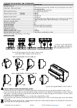
WIRING DIAGRAMS
Figure 2: Wiring example (from left to right): 2 loads, 2 loads
connected to different phases, shutter and fan coil
A1
A2
M
N
L
B1
B2
A1
A2
M
N
L
M
M
B1
B2
B1
B2
A1
A2
N
L
B1
B2
B1
A1
B2
A2
A1
A2
N
L
B1
B2
B1
B2
B1
B2
A1
A2
N
L
B1
B2
L1
L2
L1
L2
L1
L2
L3
L4
A1
A2
B1
B2
C1
C2
D1
D2
E1
E2
F1
F2
G1
G2
H1
H2
L1
L2
L3
L1
F1
F2
F3
V1
Figure 3: Mounting MAXinBOX 16 Plus on DIN rail
Removing MAXinBOX 16 Plus from DIN rail:
Attaching MAXinBOX 16 Plus to DIN rail:


