


KLIC-DD
Technical Support:
5
1.2
INSTALLATION
KLIC-DD interface connects to the KNX bus via the bus connecting terminals (1).
On the other hand, this device is connected to the internal unit PCB, using a special 5-
wire cable with S21 connectors provided in the original device packaging (4).
Once the device is provided with power supply from the KNX bus, both the physical
address and the associated application program can be downloaded.
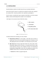
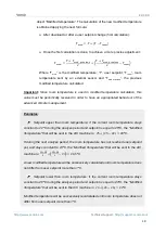
In the Figure 2, the elements scheme of KLIC-DD is shown.
Figure 2.
KLIC-DD Elements scheme.
It is described below the functionality of its main elements:
Programming button (3):
a short press on this button set the device in
programming mode, and the associated LED (2) lights red. If this button is held
while plugging the device into de KNX bus, KLIC-DD goes into secure mode.
LED indicator (2):
luminous signal that indicates the working state of KLIC-
DD. Besides lighting red when the device is in programming mode, this LED
will also light blue and green, thus indicating the status of the bidirectional
communication between KNX and the A/C unit, resulting very useful in the
installation process. Next, the meaning of each LED color is explained:
➢
Fixed red:
KLIC-DD is in programming mode.
1.- KNX connector
2.- LED indicator
3.- Programming button
4.- S21 communication cable