DIMinBOX 2CH
DIMinBOX 2CH. Two channel universal DIMMING actuator for lighting control
ZDI-DB2C
Technical Documentation
© Zennio Avance y Tecnología S.L. Draft Edition Further information
Page
1
/
4
Technical Documentation
FEATURES
Size: 80 x 90 x 60mm (4.5 DIN rail units).
2 Channel 310W (230VAC) or 160W (110VAC) for R L C loads
or 125W (230VAC) or 65W (110VAC) for dimmable CFL and
LED lamps @ 25ºC (50-60Hz).
Automatic detection of R L C load type.
Dimming pattern manual selection for CFL and LED lamps.
Optional dimming manual control.
2 analog/digital inputs.
KNX BCU integrated.
Independent control assembly, to be mounted in electrical
panels with DIN rails.
Total data saving when power failure occurs.
CE directive compliant.
GENERAL SYSTEM FEATURES
Device type
Electric operation control device
KNX supply
Voltage
29V DC SELV
Voltage range
21...31VDC
Consumption
192mW
Connection type
Typical bus connector TP1, 0,50 mm² section
External power supply
110-230V 50-60Hz
Max channel load
R L C Loads: 310W (230VAC) or 160W (110VAC) @ 25ºC; CFL and
LED lamps 125W (230VAC) or 65W (110VAC) @ 25ºC (depending
on manufacturer and model)
Min channel load rating
5W R L C loads; 5W (230VAC) or 3W (110VAC) CFL and LED lamps
Device action type
Type I
Electrical solicitations period
Long
Type of protection
IP 20, clean environment
Ambient temperature
-5 ºC to +45 ºC
Storage temperature
-20 ºC to +70 ºC
Ambient humidity
30 to 85% RH (no condensation)
Storage humidity (relative)
30 to 85% RH (no condensation)
Assembly
Independent control assembly to be mounted inside distribution
boxes or electrical panels
Power failure response
Data saving
Operation indicator
Programming LED (red) ON when pushing the programming button.
Test LED (green) ON when device is in Test mode
Weight
200 gr.
PCB CTI index
175 V
Enclosure
PC+ABS FR V0, halogen free
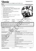
1
. Terminal block (neutral and
phase)
2
. KNX bus
connection
3
. Programming/Test LED
4
. Programming/Test push
button
5
. Analog/Digital inputs
6
. Output LED
indicator
7
. Manual Control push
button
8
. Output channels
1
Programming/test button
: push the button to set the PROGRAMMING MODE. If this button is held while plugging the device into
the KNX bus, it goes into secure mode. If this button is held more than 3 seconds, the device goes into TEST MODE.
Programming LED:
lighting red = programming mode; blinking red = safe mode; lighting green = test mode.
Output LED indicators
: lighting during a press button with manual control enabled. Moreover, it indicates the error present in the
outputs. For further information, consult the “error notifications” section.
Figure 1. DIMinBOX
2
3
4
5
6
7
8
DRAFT
EDITION


