background image


Fan Coil ‘Analog’


https://www.zennio.com                                                                   

Technical Support:


https://support.zennio.com 


2


CONFIGURATION 

Please note that the screenshots and object names shown next may be slightly different 

depending on the device and on the application program. 

2.1


CONFIGURATION 

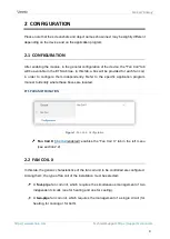
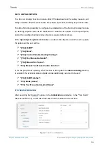
After enabling the module, in the general configuration of the device, the "Fan Coil" tab 

will be available in the ETS tab tree. In this tab, a box will be provided for each fan coil, 

in  order  to  configure  them  independently.  Refer  to  the  specific  application  program 

manual to identify where these boxes are located. 

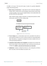
ETS PARAMETERISATION 


Figure 1. 

Fan Coil - Configuration 


Fan Coil X 

[

disabled

/enabled

]: enables the “Fan Coil X” tab in the left menu 

(see section 2.2). 

2.2


FAN COIL X 

In this tab, the generic characteristics of the fan coil unit to be controlled are configured. 

Among them, the type of fan coil of the installation must be selected: 

  A

  four-pipe 

fan  coil  unit,  which  requires  the  simultaneous  management  of  two 

independent circuits (one for heating and one for cooling).


  A

 two-pipe 

fan coil unit, which requires the management of a single circuit (for 

heating, for cooling or for both). 

Summary of Contents for Analog

Page 1: ...Fan coil Analog Control Module for Fan Coil Units with Analog Voltage Valves USER MANUAL User Manual Version 0 1 _a www zennio com...

Page 2: ...chnical Support https support zennio com 2 CONTENT Content 2 1 Introduction 3 2 Configuration 4 2 1 Configuration 4 2 2 Fan Coil X 4 2 2 1 Valve 7 2 2 2 Fan 11 2 2 3 Initialisation 14 ANNEX I Automati...

Page 3: ...ts of a four pipe fan coil unit correspond to the cooling and heating functions being therefore both modes available during the device operation The single water circuit of a two pipe fan coil unit on...

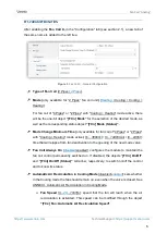
Page 4: ...dependently Refer to the specific application program manual to identify where these boxes are located ETS PARAMETERISATION Figure 1 Fan Coil Configuration Fan Coil X disabled enabled enables the Fan...

Page 5: ...heating mode Figure 2 Minimum time for mode change Fan coil always on a communication object can be provided for the switch on and the switch off of the fan coil control module as well as its corresp...

Page 6: ...available for fan coil of 4 Pipes or 2 Pipes with Cooling Heating mode active 0 3600 s 0 1440 min 0 24 h time that will elapse from fan deactivation to the opening of the new mode valve Fan Coil Alwa...

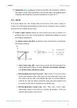
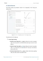
Page 7: ...t settings for cooling and heating configurations The output control value OV resulting from the scaling function is defined by the following variables 2 2 100 2 1 2 1 1 1 1 2 0 0 1 Input control valu...

Page 8: ...o With an input value VE of 70 the valve outlet value VS will be 75 Control signal change limits prevents damage to the valve due to small changes in its position and or permanent activation of the va...

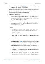
Page 9: ...ng The parameters are the following Control Signal Scaling Minimum Input Value X1 0 100 defines the minimum regulation value to be received from the thermostat that will cause the valve to start openi...

Page 10: ...t action that caused a change in valve position Notes The parameter minimum change between output signals is not considered if the command involves a change to the maximum value or a closing of the va...

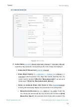
Page 11: ...et in parameters which of the two control modes must be active after download and also a time out counter to return to automatic mode after a period of time without receiving manual commands On the ot...

Page 12: ...atic 1 Manual 0 Manual 1 Automatic sets the polarity of the object that enables switching from one control mode to another FCx Fan Manual Automatic as well as its status object FCx Fan Manual Automati...

Page 13: ...ation but opens the valve the fan will be set to the minimum value Maximum Value 1 100 maximum value allowed so that for any input control value that causes an output higher than this limit the genera...

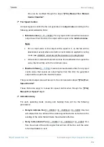
Page 14: ...fter start up If the input objects update functionality is enabled the objects on which read requests for update will be sent will be FCx On Off FCx Mode FCx Control Variable Heating Cooling FCx Fan M...

Page 15: ...start to be sent after the parameterized delay 0 600 s Send Status Object disabled enabled if enabled several checkboxes will be displayed to indicate the objects to be sent On Off disabled enabled Av...

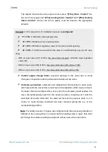
Page 16: ...orce the fan to stop Whereas if automatic air recirculation in cooling mode is not enabled or the system is operating in heating mode When receiving a control command lower than the value that activat...

Page 17: ...n and send us your inquiries about Zennio devices https support zennio com Zennio Avance y Tecnolog a S L C R o Jarama 132 Nave P 8 11 45007 Toledo Spain Tel 34 925 232 002 www zennio com info zennio...

Reviews: