4-16
DECK MECHANISM ADJUSTMENT
8.3
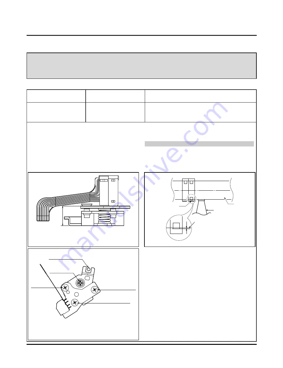
Fig. C-5-1
A/C Head Base
Fig. C-5-2
Height Adjustment
Screw(B)
Tilt Adjustment
Screw(C)
Azimuth
Adjustment
Screw(A)
X-Value Adjustment
Hole
Fig. C-5-3
A/C Head
Tape
Tape
0.2~0.25mm
P4
A/C Head Assembly
Purpose of adjustment : To ensure that audio and control signals can be recorded and
played according to the contract tract by constantly maintaining
distance between tape and head, and tape tension between the P3
post and the P4 post.
5. Audio/Control (A/C) Head Adjustment
Adjustment Procedure/Adjustment Diagrams
1) Basically use the A/C head assembly adjusted as in
SPEC.
2) Check there is crumpling and folding of the tape around
the A/C head. If it is, Turn and adjust the tilt adjusting
screw to ensure that the tape corresponds to the bottom
guide of the P4, and recheck the tape path after pro-
ceeding play for 4-5 seconds.
3) Where the tape bottom is not equal to Fig. C-5-3, Adjust
the height by using the height adjusting screw (B) and
then readjust it by using the tilt adjusting screw (C).
CAUTIONS
Always check the height of the A/C head since most ideal
height of A/C head can be obtained when the bottom part
of the tape is away 0.2 ~ 0.25mm from the bottom part of
the A/C head.
Fixtures and tools used
VCR (VCP) status
Adjustment position
• Blank Tape
(Empty Tape)
• Driver (+) Type ø 5
• Play the blank tape
(empty tape).
• Tilt adjusting screw (C)
• Height adjusting screw (B)
• Azimuth adjusting screw (A)
5-1. Prior Adjustment (performed only when no audio output appears in play of the standard test tape)
Fixed Screw
Summary of Contents for ZRY-316
Page 38: ...3 34 3 35 A B C D E F G H I J K L M N O P Q R S T 2 TUNER CIRCUIT DIAGRAM...
Page 40: ...3 38 3 39 A B C D E F G H I J K L M N O P Q R S T 4 Hi Fi CIRCUIT DIAGRAM...
Page 42: ...3 42 3 43 A B C D E F G H I J K L M N O P Q R S T 6 JACK CIRCUIT DIAGRAM...
Page 43: ...A B C D E F G H I J K L M N O P Q R S T 3 44 3 45 7 TIMER CIRCUIT DIAGRAM 2 TOOL...
Page 44: ...3 46 3 47 8 TIMER CIRCUIT DIAGRAM 3 TOOL 8 TOOL A B C D E F G H I J K L M N O P Q R S T...
Page 45: ...3 48 3 49 9 TIMER CIRCUIT DIAGRAM 4 TOOL A B C D E F G H I J K L M N O P Q R S T...
Page 46: ...3 50 3 51 10 TIMER CIRCUIT DIAGRAM 6 TOOL A B C D E F G H I J K L M N O P Q R S T...
Page 47: ...3 52 3 53 11 TIMER CIRCUIT DIAGRAM 7 TOOL A B C D E F G H I J K L M N O P Q R S T...
Page 50: ...3 58 3 59 PRINTED CIRCUIT DIAGRAMS 1 VCR P C BOARD...
Page 51: ...3 60 3 61 2 SMPS P C BOARD LOCATION GUIDE...
Page 52: ...3 62 3 63 3 JACK P C BOARD LOCATION GUIDE...
Page 54: ......
Page 64: ...3 75 3 MPEG DECODER CS98202 INTERNAL BLOCK DIAGRAM...
Page 65: ...3 76 4 DIGITAL VIDEO DECODER TVP5146PFP INTERNAL BLOCK DIAGRAM...
Page 70: ...3 83 3 84 A B C D E F G H I J K L M N O P Q R S T 2 MPEG DECODER CS98202 CIRCUIT DIAGRAM...
Page 71: ...3 85 3 86 A B C D E F G H I J K L M N O P Q R S T 3 VIDEO CONNECTOR CIRCUIT DIAGRAM...
Page 72: ...A B C D E F G H I J K L M N O P Q R S T 3 87 3 88 4 AUDIO ADC DAC INTERFACE CIRCUIT DIAGRAM...
Page 73: ...3 89 3 90 A B C D E F G H I J K L M N O P Q R S T 5 DV PART CIRCUIT DIAGRAM...
Page 78: ...3 99 3 100 PRINTED CIRCUIT DIAGRAMS 1 VDR P C BOARD TOP VIEW...
Page 79: ...3 101 3 102 2 VDR P C BOARD BOTTOM VIEW...
Page 80: ......
Page 112: ......
Page 132: ...5 20 9 LASER TURN ON SIGNAL F LIC502 PIN 52 LDEN DVD LCN201 PIN17 VRDC LCN201PIN 34...
Page 147: ...5 35 2 Disc Specification 3 Disc Materials 1 DVD ROM Single Layer Dual Layer...
Page 167: ...5 55 5 56 CIRCUIT DIAGRAMS 1 RF CIRCUIT DIAGRAM A B C D E F G H I J K L M N O P Q R S T...
Page 168: ...5 57 5 58 2 DSP CIRCUIT DIAGRAM A B C D E F G H I J K L M N O P Q R S T...
Page 169: ...5 59 5 60 3 COM CIRCUIT DIAGRAM A B C D E F G H I J K L M N O P Q R S T...
Page 171: ...5 63 5 64 PRINTED CIRCUIT DIAGRAMS 1 MAIN P C BOARD LOCATION GUIDE...


