background image

24

Installation

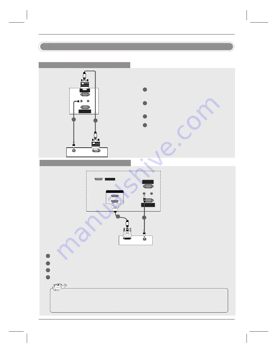
- This TV provides Plug and Play capability, meaning that the PC adjusts automatically to the TV's settings. 

PC Setup

When connecting with a D-sub 15 pin cable

1

2

3

4

Connect the RGB output of the PC to the 

RGB IN

(PC) 

jack on the set.

Connect the PC audio outputs to the 

AUDIO

IN(RGB/DVI) 

jack on the set.

Turn on the PC and the set. 

Select 

RGB-PC 

input source with using the

INPUT

button on the remote control.

RGB-PC OUTPUT

REMOTE

CONTROL IN

CONTROL IN

RS-232C IN

RS-232C IN

(CONTROL

(CONTROL & SER

 & SERVICE)

VICE)

RGB IN

(PC)

AUDIO IN

AUDIO IN

(RGB/DVI)

(RGB/DVI)

HDMI / DVI IN 

REMOTE

CONTROL IN

RS-232C IN

(CONTROL & SERVICE)

RGB IN

(PC)

AUDIO IN

(RGB/DVI)

SERVICE

 AUDIO 

1

2

PC

When connecting with a HDMI to DVI cable

1

2

3

4

Connect the DVI output of the PC to the 

HDMI IN 1(DVI) 

jack on the set.

Connect the audio outputs of the PC to the 

AUDIO IN(RGB/DVI)

jack on the set.

Turn on the PC and the set. 

Select 

HDMI1/DVI 

input source with using the 

INPUT

button on the remote control.

DVI-PC OUTPUT

REMOTE

CONTROL IN

RS-232C IN

(CONTROL & SERVICE)

RGB IN

(PC)

AUDIO IN

(RGB/DVI)

REMOTE

REMOTE

CONTROL IN

CONTROL IN

RS-232C IN

(CONTROL & SERVICE)

RGB IN

RGB IN

(PC)

AUDIO IN

(RGB/DVI)

SERVICE

SERVICE

HDMI IN 

HDMI IN 

1(DVI)

1(DVI)

2

 AUDIO 

PC

• If the PC has a DVI output and no HDMI output, a separated audio connection is necessary.
• If the PC does not support Auto DVI, you need to set the output resolution appropriately. To get the

best picture quality, adjust the output resolution of PC graphics card to 1024x768, 60Hz.

1

2

Summary of Contents for Z42P3 and

Page 1: ...as determined that this product meets the ENER GY STAR guidelines for energy efficiency E EN NE ER RG GY Y S ST TA AR R i is s a a s se et t o of f p po ow we er r s sa av vi in ng g g gu ui id de el...

Page 2: ...allation This equipment generates uses and can radiate radio frequency energy and if not installed and used in accordance with the instructions may cause harmful interference to radio communications H...

Page 3: ...near any heat sources such as radiators heat registers stoves or other apparatus including amplifiers that produce heat 9 Do not defeat the safety purpose of the polarized or grounding type plug A po...

Page 4: ...e CAUTION concerning the Power Cord Most appliances recommend they be placed upon a dedicated circuit that is a single outlet circuit which powers only that appliance and has no additional outlets or...

Page 5: ...de Black Level 37 Video Reset 38 Audio Language 39 Auto Sound Control EZ Sound 39 40 Manual Sound Control EZ Sound User option 41 Balance 41 TV Speakers On Off Setup 2 Warning 3 4 Safety Instructions...

Page 6: ...on Text 47 Caption Option 47 Low Power 48 ISM Image Sticking Minimization Method 49 50 Parental Lock Setup 51 56 External Control Device Setup 57 58 IR Codes 59 Programming the Remote 60 Programming C...

Page 7: ...l interface cables D sub 15 pin cable with ferrite cores to maintain standard compliance for the product 1 5V 1 5V EN TE R VO L FLA SH BA CK MU TE CH TIM ER P 3 6 EN TE R TV TV INP UT INP UT DV D RA T...

Page 8: ...elow may be somewhat different from your TV CH CH VOL OL ENTER ENTER MENU MENU INPUT INPUT CHANNEL D E Buttons VOLUME F G Buttons ENTER Button MENU Button INPUT Button Remote Control Sensor Power Stan...

Page 9: ...IN Connect a component video audio device to these jacks AV OUT Connect a second TV or monitor AV Audio Video IN 1 Connect audio video output from an external device to these jacks S VIDEO Connect S...

Page 10: ...Component 1 2 RGB PC HDMI1 DVI and HDMI2 input sources are linked automatically only if these are connected Turns your TV or any other programmed equipment on or off depending on the mode Change the...

Page 11: ...te type of sound for type of program green G G p p 3 39 9 Adjust the screen position size and phase in PC mode yellow G G p p 2 26 6 Display information at the top of the screen blue Control video cas...

Page 12: ...ye bolts or TV brackets and bolts to tighten the product to the wall as shown in the picture If your product has the bolts in the eye bolts position loosen the bolts Secure the wall brackets with the...

Page 13: ...picture shown below may be somewhat different from your TV GROUNDING Ensure that you connect the earth ground wire to prevent possible electric shock If grounding methods are not possible have a qual...

Page 14: ...When connecting cables to the set Do not disengage the lock C This may cause the set to fall causing serious bodily injury and serious damage to the set 3 Basic Connection Basic Connection C Image sho...

Page 15: ...it as shown Connect the cables as necessary To connect an additional equipment see the External equipment Connections section Reinstall the CABLE MANAGEMENT as shown 1 2 3 How to arrange the cable Fo...

Page 16: ...e antennas Cable TV Wall Jack RF Coaxial Wire 75 ohm Bronze Wire Bronze Wire Turn clockwise to tighten Antenna RF Coaxial Wire 75 ohm In a poor signal area to improve picture quality purchase and inst...

Page 17: ...OUTPUT SWITCH ANT OUT ANT IN HDMI DVI IN ANTENNA CABLE IN REMOTE CONTROLIN RS 232C IN CONTROL SERVICE RGB IN PC AUDIO IN RGB DVI VIDEO VIDEO AUDIO AUDIO VIDEO VIDEO AUDIO AUDIO MONO S VIDEO S VIDEO A...

Page 18: ...the VCR owner s manual Select AV1 input source with using the INPUT button on the remote control If connected to AV IN2 select AV2 input source Do not connect to both Video and S Video at the same ti...

Page 19: ...s manual for operating instructions When connecting with a HDMI cable 1 2 3 Connect the HDMI output of the DVD to the HDMI IN 1 DVI or 2 jack on the set Select HDMI1 DVI or HDMI2 input source with usi...

Page 20: ...e remote control If connected to COMPONENT IN 2 select Component 2 input source Refer to the DVD player s manual for operating instructions Component Input ports To get better picture quality connect...

Page 21: ...IO IN RGB DVI HDMI DTV OUTPUT REMOTE CONTROLIN RS 232C IN CONTROL SERVICE RGB IN PC AUDIO IN RGB DVI REMOTE REMOTE CONTROLIN CONTROLIN RS 232C IN RS 232C IN CONTROL CONTROL SER SERVICE VICE RGB IN RGB...

Page 22: ...2C IN RS 232C IN CONTROL CONTROL SER SERVICE VICE RGB IN RGB IN PC PC AUDIO IN AUDIO IN RGB DVI RGB DVI RS 232C IN CONTROL SERVICE VIDEO AUDIO VIDEO AUDIO S VIDEO AV IN 1 AV OUT COMPONENT IN DIGITALAU...

Page 23: ...o equipment stereo system via the Digital Audio Output Optical port CAUTION Do not look into the optical output port Looking at the laser beam may damage your vision 1 2 AV Out Setup 1 2 Connect the s...

Page 24: ...VI SERVICE AUDIO 1 2 PC When connecting with a HDMI to DVI cable 1 2 3 4 Connect the DVI output of the PC to the HDMI IN 1 DVI jack on the set Connect the audio outputs of the PC to the AUDIO IN RGB D...

Page 25: ...VI mode If noise is present change the PC or HDMI DVI mode to another resolution change the refresh rate to another rate or adjust the brightness and contrast on the menu until the picture is clear If...

Page 26: ...B PC or HDMI DVI to PC input and checking the screen quality Press the ADJUST button and then use D D E E button to select Resolution POSITION SIZE or PHASE Press ENTER button and then use D D E E F F...

Page 27: ...e MUTE or VOL button Press the CH or NUMBER buttons to select a channel number The menus can be shown on the screen in the selected language First select your language On Screen Menus Language Selecti...

Page 28: ...differ slightly from what is shown in this manual How to adjust the OSD screen EZ Scan Manual Scan Channel Edit DTV Signal Input Source Input Label Set ID EZ Picture Color Temperature DB Advanced Vid...

Page 29: ...n to add or delete for the channel number Press EXIT button to return to TV viewing or press MENU button to return to the previous menu 1 2 3 4 5 6 Automatically finds all channels available through a...

Page 30: ...ed and then you can add or delete the channel to from the Favorite List Channel Edit Press the MENU button and then use D D E E button to select the SETUP menu Press the G G button and then use D D E...

Page 31: ...V cable TV VCR DVD or any other devices that are connected to your TV Input Source Press the MENU button and then use D D E E button to select the SETUP menu Press the G G button and then use D D E E...

Page 32: ...tton and then use D D E E button to select the source AV1 2 Component1 2 RGB PC HDMI1 DVI or HDMI2 Press the F F G G button to select the label Press EXIT button to return to TV viewing or press MENU...

Page 33: ...d User 2 your own set tings You can also use the VIDEO menu to adjust EZ Picture Press the EXIT button to save and return to TV viewing 1 2 Color Temperature Control Choose one of three automatic colo...

Page 34: ...ed 0 G Green 0 Blue 0 Press the MENU button and then use D D E E button to select the VIDEO menu Press the G G button and then use D D E E button to select Color Temperature Press the G G button and t...

Page 35: ...nd then use D D E E button to select the VIDEO menu Press the G G button and then use D D E E button to select DB Press the G G button and then use D D E E button to select Auto or Manual Press EXIT b...

Page 36: ...olor Temperature DB Advanced Video Reset EZ Picture Color Temperature DB Advanced G Video Reset Cinema 3 2 Mode Off Black Level Low Press the MENU button and then use D D E E button to select the VIDE...

Page 37: ...n to select the VIDEO menu Press the G G button and then use D D E E button to select Video Reset Press the G G button to reset the Video menu options to original values 1 2 3 Video Reset EZ Picture C...

Page 38: ...utton to select the AUDIO menu Press the G G button and then use D D E E button to select Audio Language Press the G G button and then use D D E E button to select English Spanish or French Press EXIT...

Page 39: ...ron ment Press the EZ SOUND button repeatedly to select the appropriate sound setup as shown below Normal Stadium News Music Theater and User your own settings You can also adjust EZ Sound in the AUDI...

Page 40: ...ous menu 6 SRS TruSurround XT Takes advantage of any multi channel format without needing to add extra speakers or equipment Dialog clarity bass enrichment and the addition of stereo audio enhancement...

Page 41: ...return to TV viewing or press MENU button to return to the previous menu Balance 1 2 3 4 TV Speakers On Off Setup Turn TV speakers off if using external audio equipment Feature turns the TV Speakers o...

Page 42: ...hen use D D E E button to select the TIME menu Press the G G button and then use D D E E button to select Manual Clock Press the G G button and then use F F G G button to select either the year date o...

Page 43: ...to set the hour Press the G G button and then use D D E E button to set the minutes For only On Timer function Press the G G button and then use D D E E button to select the channel at turn on Press...

Page 44: ...ress the G G button and then use D D E E button to select Auto Off Press the G G button and then use D D E E button to select Off or On Press EXIT button to return to TV viewing or press MENU button t...

Page 45: ...r picture proportion to match the source s image 4 3 Choose 4 3 when you want to view a picture with an original 4 3 aspect ratio 16 9 Adjust the picture horizontally in a linear proportion to fill th...

Page 46: ...G button and then use D D E E button to select available cap tion languages English Spanish or French Press EXIT button to return to TV viewing or press MENU button to return to the previous menu 1 2...

Page 47: ...e Edge Color Select a color for the edges Press EXIT button to return to TV viewing or press MENU button to return to the previous menu 1 2 3 4 5 Low power reduces the power consumption of plasma disp...

Page 48: ...set to Normal White Wash White Wash removes permanent images from the screen Note An excessive permanent image may be impossible to clear entirely with White Wash To return to normal viewing press the...

Page 49: ...cautioned R Restricted NC 17 No one 17 and under admitted X Adult only If you set PG 13 G and PG movies will be avail able PG 13 R NC 17 and X will be blocked Ratings for Television programs includin...

Page 50: ...g MPPA Blocks movies according to the movie rat ings limits specified so children cannot view certain movies You can set the ratings limit by blocking out all the movies with the rat ings above a spec...

Page 51: ...ard D Sub 9 3 2 5 4 6 7 8 TV D Sub 9 Connect the RS 232C input jack to an external control device such as a computer or an A V control system and control the Monitor s functions externally Connect the...

Page 52: ...otocol OK Acknowledgement The Monitor transmits ACK acknowledgement based on this format when receiving normal data At this time if the data is data read mode it indicates present status data If the d...

Page 53: ...t using the RATIO button on remote control or in the Option menu Transmission k c Set ID Data Cr Acknowledgement c Set ID OK Data x 04 Screen Mute Command2 d G To select screen mute on off Transmissio...

Page 54: ...Cr Acknowledgement k Set ID OK Data x 12 OSD Select Command2 l G To select OSD On Screen Display on off Transmission k l Set ID Data Cr Acknowledgement Data 0 OSD off 1 OSD on l Set ID OK Data x 14 Tr...

Page 55: ...be done by only physical channel In this case using phys ical channel bit must be low 0 But if the channel band is ATSC air or ATSC cable there are two cases that physical channel enable or disable If...

Page 56: ...l Add m b Set ID Data Cr b Set ID OK Data x b Set ID NG Data x Acknowledgement 22 Key Command m c G To send IR remote key code Transmission Data Key code Refer to page 58 m c Set ID Data Cr c Set ID O...

Page 57: ...e Data code Data code TC Tf T1 C0 Carrier frequency FCAR 1 TC fOSC 12 Duty ratio T1 TC 1 3 Repeat frame C1 C2 C3 C4 C5 C6 C7 C0 C1 C2 C3 C4 C5 C6 C7 D0 D1 D2 D3 D4 D5 D6 D7 D0 D1 D2 D3 D4 D5 D6 D7 Rep...

Page 58: ...R C Button R C Button R C Button R C Button R C Button R C Button R C Button R C Button R C Button R C Button R C Button R C Button Discrete IR Code Component1 Input Selection Discrete IR Code Compone...

Page 59: ...the POWER button to see if the component responds properly If not the remote requires pro gramming to operate the device Turn on the component to be programmed then press the correspond ing MODE butt...

Page 60: ...X 031 033 034 041 067 068 MARANTZ 012 031 033 067 069 MARTA 101 MATSUI 027 030 MEI 031 033 MEMOREX 003 010 014 031 033 034 053 072 101 102 134 139 MGA 045 046 059 MINOLTA 013 020 MITSUBISHI 013 020 04...

Page 61: ...ing problems tune to another station Station signal is weak reorient antenna to receive weaker station Check for sources of possible interference Lines or streaks in pictures Check antenna Change the...

Page 62: ...oes not indicate a fault with the product No output from one of the speakers Adjust Balance in menu option Screen color is unstable or single color Check the signal cable Reinstall the PC video card T...

Page 63: ...with a soft dry lint free cloth Please do not use a wet cloth If you expect to leave your TV dormant for a long time such as a vacation it s a good idea to unplug the power cord to protect against po...

Page 64: ...Height x Depth Weight with stand without stand with stand without stand Power requirement Television System Program Coverage External Antenna Impedance Operating Temperature Operating Humidity Storage...

Page 65: ......

Page 66: ......

Page 67: ...of repair or replacement under these excluded circumstances shall be borne by the consumer WARRANTY PERIOD LABOR ONE YEAR from the Date of Purchase PARTS ONE YEAR from the Date of Purchase Effective D...

Page 68: ...unit to Zenith Parts and service in accordance with the Zenith warranty are Zenith s responsibility and will be provided without charge Other service requirements will be at the owner s expense If yo...

Reviews: