Zenith VRB210 Operating Manual Download Page 3

IMPORTANT SAFETY INSTRUCTIONS

SA F E T Y   T I P S

P A G E   3

1.

Read Instructions

Read all of the safety and operating instructions before
operating the product.

2.

Retain Instructions

Keep all safety and operating instructions for future
reference.

3.

Heed Warnings

Follow warnings on the product and in the operating
guide.

4.

Follow Instructions

Follow all operating and use instructions.

5.

Cleaning

Unplug this product from the wall outlet before 
cleaning. Do not use liquid cleaners or aerosol cleaners.
Use a damp cloth for cleaning.

6.

Attachments

Do not use attachments not recommended by product
manufacturer as they may cause hazards.

7.

Water and Moisture

Do not use this product near water—for example, near
a bathtub, wash bowl, sink, or laundry tub, in a wet
basement, or near a swimming pool.

8.

Accessories

Do not place product on an unstable cart, stand, 
tripod, bracket, or table. Product may fall, causing 
serious injury to a child or adult, and serious damage
to the product. Use only with a cart, stand, tripod,
bracket, or table recommended by the manufacturer or
sold with the product. Any mounting of product should
follow manufacturer’s instructions and should use a
mounting accessory recommended by manufacturer.

9.

Transporting Product

Move product and cart combinations
with care. Quick stops, excessive
force, and uneven surfaces may cause
product and cart combination to
overturn.

10. Ventilation

Slots and openings in cabinet must not be blocked or
covered. They are provided for ventilation, to ensure
reliable operation, and to protect from overheating.
Never block openings by placing product on a bed,
sofa, rug, or other similar surface. Do not place product
in built-in installation such as a bookcase or rack
unless proper ventilation is provided or manufacturer’s
instructions have been adhered to.

11. Power Sources 

Operate product only from type of power source 
indicated on marking label. If you are not sure of the
type of power supply to your home, consult your 
product dealer or local power company. For products
intended to operate from battery power or other
sources, refer to manual.

12. Line-Cord Polarization

Product is equipped with a polarized alternating-
current line plug (a plug having one blade wider than
the other). As a safety feature, this plug will fit into
power outlet only one way. If you’re unable to insert
plug fully into outlet, try reversing the plug. If plug
still fails to fit, contact an electrician to replace your
obsolete outlet. Do not defeat safety purpose of 
polarized plug.

13. Power-Cord Protection

Route power-supply cords so
they are not likely to be
walked on or pinched by items
placed upon or against them,
paying particular attention to
cords at plugs, convenience
receptacles, and the point
where they exit from product.

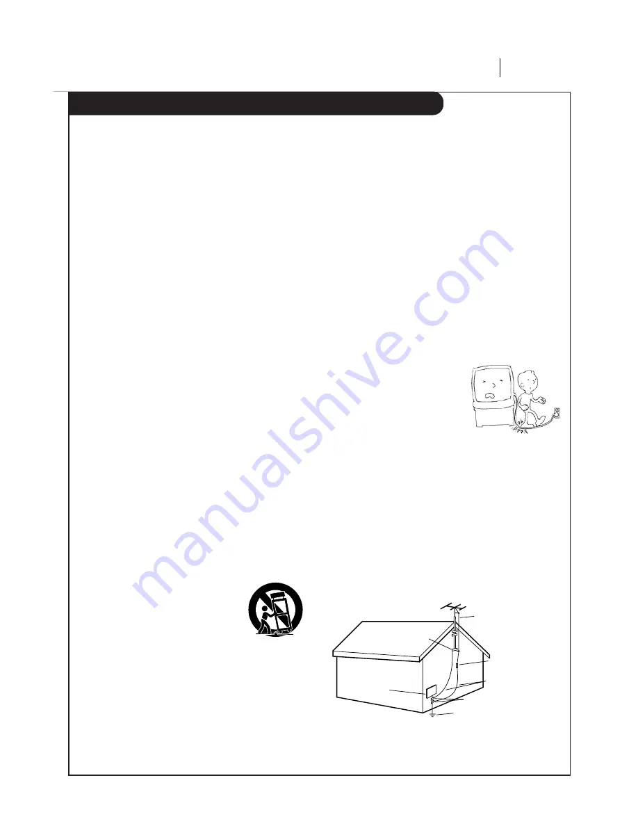
14. Outdoor Antenna Grounding

If an outside antenna or cable system is connected to
this product, be sure antenna or cable system is
grounded so as to provide some protection against
voltage surges and built-up static charges. Article 810
of the National Electrical Code (USA), ANSI/NFPA 70
provides information on grounding of mast and 
supporting structure, grounding of lead-in wire to an
antenna discharge unit connection to grounding 
electrodes, and requirements for grounding electrode. 
( See Fig. 1 below. )

These simple precautions will help ensure that you get many years of safe enjoyment from your new product.

Antenna Lead-in Wire

Antenna Discharge Unit
NEC Section 810-20 

Grounding Conductors
NEC Section 810-21

Ground Clamps

Power Service Grounding 
Electrode System 
NEC Art 250, Part H

Ground

Clamp

Electric Service

Equipment

NEC:  National Electrical Code

Antenna grounding per NEC Code, ANSI/NFPA 70

Fig. 1

Summary of Contents for VRB210

Page 1: ...rs VRB210 VRB410 VRB420 o p e r a t i n g g u i d e w a r r a n t y As an ENERGY STAR Partner Zenith Electronics Corporation has determined that this product meets the ENERGY STAR guidelines for energ...

Page 2: ...le protection against harmful interference when the equipment is operated in a residential installation This equipment generates uses and can radiate radio frequency energy and if not installed and us...

Page 3: ...is provided or manufacturer s instructions have been adhered to 11 Power Sources Operate product only from type of power source indicated on marking label If you are not sure of the type of power sup...

Page 4: ...or Ceiling Mounting Mount product to wall or ceiling only as recommended by manufacturer 21 Replacement Parts When replacement part s are required be sure service technician has used replacement part...

Page 5: ...Camcorder Connected to VCR 21 Playing Tapes 22 23 Instant Recording 24 26 Recording While You re Away 27 TROUBLESHOOTING 28 30 SPECIFICATIONS 31 INDEX Audio Menu 19 Auto Channel Search 11 18 Connecti...

Page 6: ...X X X Auto Playback System X X X Auto Manual Digital Tracking X X X Instant Recording X X X Timer Controlled Recording X X X Auto Playback Tape Speed Adjust X X X Forward Reverse Slow Motion N A X X V...

Page 7: ...IN OUT OUT IN R L AUDIO VIDEO VHF UHF CATV ANT IN ANT IN OUT TO TV VHF UHF CATV VIDEO R AUDIO L OUT IN OUT CH3 CH4 IN Turn off power or unplug VCR before making any connections Back Panel of Typical C...

Page 8: ...IO VIDEO IN VHF UHF CATV A V cable is not provided with VCR ANT IN OUT TO TV VHF UHF CATV VIDEO R AUDIO L OUT IN OUT CH3 CH4 IN Back Panel of Typical Monaural TV Note If the back panel on your TV is d...

Page 9: ...YBACK HI FI RECORD STEREO How to Access Menus Menu operation is easy just follow the instructions shown at the bottom of the menu 1 Press MENU to see main menu 2 Press NUMBER 1 2 3 or 4 to see desired...

Page 10: ...play press the TV VCR button on remote repeatedly until the VCR indicator light appears in the VCR s front panel display Press MENU on the remote to see the main menu Select SpeakEZ Function On Off A...

Page 11: ...UP Menu page 18 for details Use CH ADD DEL to Create Favorite Channels Optional Use CH ADD DEL to change the list of active channels found when using AUTO PROGRAM so you can list your favorites See CH...

Page 12: ...UDIO Menu for details SpeakEZ CLOCK 1 TIMER 2 SETUP 3 AUDIO 4 Press number keys QUIT exit CLOCK MENU AUTO DAYLIGHT SAVING ON 1 ON 2 OFF MANUAL CLOCK SET 3 Press number keys QUIT exit MAIN MENU Press N...

Page 13: ...p ep ch stop eject z e n i t h LED Front Panel Indicators power cst in vcr rec timer A Cassette is in the VCR VCR is in Timer recording Remote Window Keep this area free of obstruction VCR is recordin...

Page 14: ...appears press ENTER repeatedly to see abbreviated displays as follows 1 Press ENTER to see Status Display 2 Press ENTER a second time to show only the tape counter position 3 Press ENTER a third time...

Page 15: ...compartment Note All VCR operations and menu options can be accessed by using the remote control CH Channel Selectors Also selects AUX A V input channel CM SKIP Fast forwards picture search through 3...

Page 16: ...k in the VCR to the current date and time Notes The clock must be set before you can record using the TIMER menu You may have to reset the clock and other features if a power outage lasts for more tha...

Page 17: ...iday CHANNEL OPTIONS To select an AUX channel select the next highest or lowest channel programmed in the VCR with the CH SPEED OPTIONS SP or EP The SP mode determines how much tape is left and switch...

Page 18: ...o select the channel to be edited e g to ADD channel 3 press 3 then ENTER Press ENTER to ADD or DEL Delete channels to create your own list of favorite channels SOURCE Selects TV CATV or AUX as the so...

Page 19: ...ral sound regardless of the audio format present on the tape RECORD Select the STEREO MONO or SAP for recording a program STEREO records sound from the left and right audio tracks in stereophonic form...

Page 20: ...x Selecting Channels at the VCR when VCR is ON 1 Turn TV and VCR on 2 Place VCR in VCR mode by pressing the TV VCR button on the remote control repeatedly until the VCR indicator appears in the front...

Page 21: ...the VCR Channel down lower than the lowest channel or Channel up above the highest to select AUX You can also choose the SETUP menu as described in How to Access Menus on page 9 Press 3 for the SETUP...

Page 22: ...el 3 or 4 at the TV or select the TV s AUX Auxiliary source to see the picture if you are using the A V jacks Refer to your TV operating manual Unloading the Cassette from the VCR 1 Press STOP if the...

Page 23: ...normal tape playing Note When the reverse slow mode continues for more than 30 seconds the VCR will automatically change to play mode Tape Rewind and Fast Forward While in Stop mode Press and release...

Page 24: ...select the cable box output channel usually 3 or 4 at the VCR Select cable box channels at the cable box Insert a VHS cassette tape into the VCR Press SP EP to select recording speed if desired Recor...

Page 25: ...l Select channel 3 or 4 at the TV If you have connected your VCR to the TV s A V input jacks select the A V source at the TV for a better picture Select the channel to be watched and recorded at the V...

Page 26: ...cassette tape into the VCR Press SP EP to select recording speed if desired Recording speed is always SP unless you select EP Press REC ITR until recording begins REC indicator light appears in the V...

Page 27: ...the channel to be recorded Keep your cable box on when using the Timer to record Enable the Timer by pressing POWER to turn off the VCR The TIMER indicator light appears in the VCR front panel to ind...

Page 28: ...n TV to Audio Video In or tune TV to Channel 3 or 4 as appropriate Press the TV VCR button on remote repeatedly to choose VCR mode VCR indicator light appears in VCR front panel Disconnect VCR power c...

Page 29: ...ff to enable timer This is the normal indication that the VCR is in TIMER mode Channel Tuning Problems Observed Condition Some channels are skipped over when using CH Picture and sound are weak or mis...

Page 30: ...ge the VCR and cassettes used in the VCR Snow streaking in picture and horizontal pulling indicate the need for professional video head cleaning See your Zenith approved service center for cleaning Ca...

Page 31: ...5 ohms VHF 75 ohms VHF Output Signal Channel 3 or 4 Channel Coverage VHF 2 13 UHF 14 69 CATV 1 125 4A A W W 1 W 84 A 5 A 1 VIDEO Video Signal System EIA Standard 525 lines 60 fields NTSC type color si...

Page 32: ...ers is due to excessive rewinding Prolong the life of your video equipment with our rewinder ONLY 14 99 PLUS 6 95 SHIPPING HANDLING VHS TAPE REWINDER ZEN 901 Broken or lost remote Need a second remote...

Page 33: ...Notes NOTES P A G E 3 3...

Page 34: ...Notes P A G E 3 4 NOTES...

Page 35: ...Notes NOTES P A G E 3 5...

Page 36: ...operation of your set and how to adjust the customer controls Carry In Service The video product must be taken to a U S or Canadian Zenith authorized service center for warranty service and must be pi...

Reviews: