background image

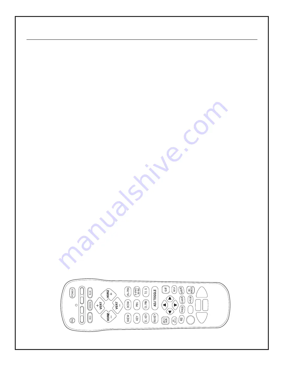
1.  When you enter the setup mode, the system is in the

“Geometry Mode” (the shape controls adjust all three
colors at the same time). To adjust an individual color
(i.e. Red to adjust SKEW), you must press the “Red
Select” key. This will put the system into the
“Convergence Mode” (the shape controls adjust one
color at a time). To return to the Geometry Mode, you
must press the “Red Select” key a second time. 

2.  When you are adjusting all colors (“geometry mode”)

the little arrow keys at the bottom are for video phase
adjust only. When they are pressed, the remote will
switch the geometry control to phase. If the arrow keys
have not been touched for a few seconds, the remote
will automatically switch back to the geometry control
you were last using before using the small arrows. 

3.  When you are adjusting an individual color (“conver-

gence mode”) the little arrow keys at the bottom are
for DC Centering only. When they are pressed, the
remote will switch the convergence control to DC
Centering. If the arrow keys have not been touched for 
a few seconds, the remote will automatically switch
back to the convergence control you were last using
before using the small arrows. 

4.  The setup controls, in the on screen display, are usually

labeled with Horz/Vert, T/L (top/left), or B/R 
(bottom/right) and a number value indicating the 
current setting. 

5.  If you want to see what effect the “new setting” 

compared to the “stored setting” has on the display,
press the “ADJ TOGGLE” key on the remote. Adjust tog-
gle will allow you to switch between the two settings
before committing to a change. 

6.  After making your changes and adjustments, be sure

you SAVE THE NEW SETTINGS. If a major change has
been made, new module, new CRT, or a change in the 
physical setup, you must re-adjust and store the 
geometry/setup for each of the formats and aspect
ratios being used. 

7. To escape from the setup mode, without saving any

P A G E   1 4

changes, press the “Quit” key twice.

8.  Caution - shut all the PRO900X timers and signal source

power conserve features off before starting 
convergence. If the video signal is lost, you will quit 
convergence mode with no chance to save your work.

9.  To display the Forced Mode Menu press “SETUP” and

“GREEN SELECT”.

10. To display the current sync and video format being used

press, “GREEN MUTE”. 

11.To see the elapsed time display, press and hold “LIN

C/LI-LIN”, until the regular menu disappears, and then
press the “TIMER” or “H-Pulse” key.

12.To set the unit IR Code (for use when multiple units are

in the area), press and hold “LIN C/LI-LIN”, until the
regular menu disappears, and then press “T/LS”, “T/LS”,
“T/LS”, “T/LS”, and “ADJ TOGGLE”. 

13. Copying Formats Procedure

Copy the setup information (Convergence, blanking,
phase, chromatics, and aspect ratio) from one defined
format to another defined format. Procedure quickly
copies unrecognized new formats or existing formats to
one of the five available “Customer” defined format
spaces. The ten factory format presets cannot be over-
written. To display the Copy Format Menu, press 
“R-MUTE”.  Use the Left/Right arrows to select the for-
mat you want to copy. Use the Up/Down arrows to
change the menu option from “Copy From” to “Copy To”.
Use ENTER to initate copying the format to the newly
specified customer format (Customer 1, Customer 2,
etc.) If a format already exists in the selected Customer
format space, it will be overwritten by the new format
when ENTER is pressed. QUIT exits the menu without
making any changes.

14. To aid with the alignment procedure, it is recommended

that you mark the center of the screen and the center
of all four sides with masking tape. Use “drafting” type
tape that will not leave any marks. This will give you 
calibration points for convergence and CRT alignments.

SETUP MODE NOTES AND CAUTIONS 

206-3634

Summary of Contents for Presentation PRO900X

Page 1: ...HD Projection Display Installation and Setup Guide for System Installer Model PRO900X PresentationTM Series PresentationTM is a registered trademark of Zenith Electronics Corporation...

Page 2: ...rmined by turning the equipment off and on the user is encouraged to try to correct the interference by one or more of the following measures Reorient or relocate the receiving antenna Increase the se...

Page 3: ...f Red and Blue onto Green 27 Notes 28 PLACEMENT CONSIDERATIONS Room Light Ideally the PRO900X should be placed in a low light envi ronment Picture quality and the ability to see the project ed images...

Page 4: ...rent 120 volt 60 Hertz AC or 230 volt 50 60 Hertz AC Do not attempt to operate it on DC current The PRO900X is configured at the factory for 120 volt 60 Hz operation A service adjustment is necessary...

Page 5: ...tion World Wide Multi standard Video System PAL M N PAL B G NTSC Aspect Ratio Correction Multi Frequency Multi Format High Definition System 15 to 50 kHz 75 MHz dot clock Addressability via IR for mul...

Page 6: ...apters cables or connectors shown are not provided with the PRO900X See your computer dealer for your special requirements To hook up a VCR DVD play er or other video source use standard video connec...

Page 7: ...P A G E 7 3276 A STANDARD CONNECTIONS CONNECTOR PIN WIRING REFERENCE...

Page 8: ...h SELECTS MENU OPTIONS REMOTE CONTROL WINDOW S VIDEO INPUT JACK COMMUNICATIONS PORT INTER CONNECT JACK RJ 11 Loop Out Loop In Setup Switch Set LOOP switch to Out if routing composite video to a second...

Page 9: ...ry replace the batteries with two high quality alkaline size AAA batteries Vertical and Horizontal Adjusts selected geometry convergence characteristics Adjustment Select Keys Adjusts selected geometr...

Page 10: ...omized setup has a separated memory location for each aspect ratio 4 X 3 letter box compressed and 16 X 9 You must set up and converge the system for each aspect ratio that will be used The five custo...

Page 11: ...and understand the setup section before you attempt to install a PRO900X system you will find tables and examples of the required installation data for a successful installation Also the user Operati...

Page 12: ...3276 A P A G E 1 2 TOP INSIDE VIEW...

Page 13: ...ontrol The mode functions at the top CABLE VCR AUX and TV are standard MBR programmable functions The SETUP mode is only for PRO900X setup convergence use To use the normal user menu Source Setup or V...

Page 14: ...ry setup for each of the formats and aspect ratios being used 7 To escape from the setup mode without saving any P A G E 1 4 changes press the Quit key twice 8 Caution shut all the PRO900X timers and...

Page 15: ...al nega tive vertical analog sync III FREQUENCY RANGE 1 SYNC ON GREEN Horizontal component 15kHz to 50kHz Vertical component 50 to 100 Hz 2 HORIZONTAL COMPOSITE Horizontal component 15kHz to 50kHz Ver...

Page 16: ...3276 A NOTES P A G E 1 6...

Page 17: ...e the height ASPECT RATIOS OF COMMON PROJECTION FORMATS H W 1 00 1 00 Overhead and opaque projection 1 00 1 78 or 9 16 High Definition Television HDTV Anamorphic Video 1 00 1 33 or 3 4 LCD and CRT vid...

Page 18: ...the PRO900X recognizes all the source signals d Verify that the PRO900X operates correctly e Turn the PRO900X off and disconnect the AC power 2 Set Floor Ceiling and Front Rear Configuration Refer to...

Page 19: ...P A G E 1 9 3276 A SETUP REFERENCES Setup Menus 9 1505 Module 9 1510 Module 9 1509 Module Top Edge Top View...

Page 20: ...Note Distance A is measured from the cabinet panel front directly below the green CRT lens 2 Calculate the Display Center B from a reference line projected from the bottom of the cabinet Display Cente...

Page 21: ...P A G E 2 1 3276 A SYSTEM ALIGNMENT Mount Bracket Center 11 from Front Panel Under the Green CRT Center 11...

Page 22: ...shows a need for astimatator alignment perform steps a l below Astigmatator Alignment Procedure a Set the display sync mode to Forced Mode 6 HDTV33 and select a cross hatch or dot pattern b Cut off Re...

Page 23: ...rocedure Note Throughout this procedure pay no attention to the corners of the image g Adjust the focus mechanically and electrically to get the best overall image h Cover the Green lens and uncover t...

Page 24: ...rn to the convergence mode and set up the Red and Blue display with precision Converge the Red display to the Green display using all necessary controls b Now store the completed setup 5 Video Blankin...

Page 25: ...et for straight right edge line F H corner F H move center D is stable 18 S ING H S Set for straight right edge line F H middle areas O Q move opposite and center D and ends F H are stable 19 T L KEY...

Page 26: ...3276 A P A G E 2 6...

Page 27: ...EY V Top Key Balance error with Green at top corners E F straight with respect to screen border left and right move in opposite directions center A is stable 21 T L KEY V Top Pin Match Green at top ed...

Page 28: ...206 3634 Copyright 2000 Zenith Electronics Corporation 1000 Milwaukee Avenue Glenview Illinois 60025 2495 NOTES...

Reviews: